

Catalog · How the catalog works
NVRAMancer

NVRAMancer - a necromancer for non-volatile memory. Serial flash / EEPROM programmer for CH347, CH341A, EZP2023+ and more.
- ★ 2 on GitHub
Anyone may press Interesting, signed in or not. It helps others find this project.
README
Asprogrammer PN
A flash programmer that refuses to guess your chip's voltage.
SPI NOR · SPI NAND · I²C EEPROM · Microwire — across nine programmers.
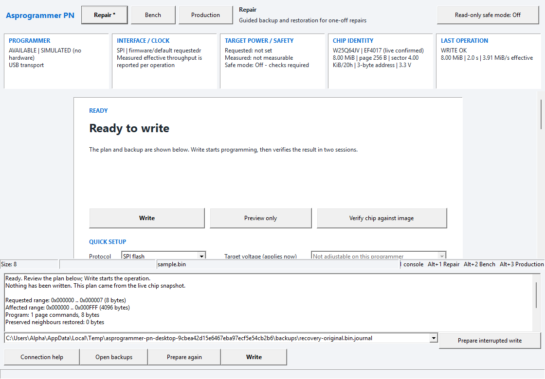
The Repair workspace preparing an eight-byte image on the built-in simulated programmer, without physical hardware.
<table>
<tr>
<td width="46%">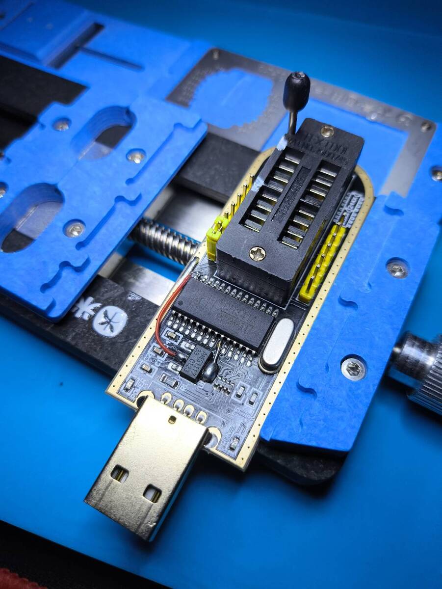 </td>
<td>
The hardware is why this program is careful.
That is a CH341A in a repair jig — and it has a red wire soldered across it. That mod exists because these boards are widely reported to drive 5 V logic on the SPI lines while VCC reads 3.3 V. Two boards that look identical can behave completely differently, and no software can see the difference.
So Asprogrammer PN does not claim to know things it cannot measure. It reports the rail it asked for and the rail it measured as separate facts, and where the hardware has no sensor it says "not measurable on this programmer" instead of showing a number that reads like a confirmation.
Unknown voltage is shown in the workspace, beside the controls needed to select its datasheet value.
</td> </tr> </table>
Download and upgrade
Download the Windows ZIP from the latest release,
extract the complete archive, and run AsprogrammerPN.exe. Keep its bundled
DLLs and data files together. No installer is required. Release assets include
SHA256SUMS.txt; release verification describes
checksum and provenance checks.
Asprogrammer PN 4.45.0.0 replaces the NVRAMancer application name. Update
shortcuts and scripts to AsprogrammerPN.exe or AsprogrammerPNCLI.exe.
The GitHub repository address remains patnawa/NVRAMancer.
- Explicit backup-directory settings take priority. Otherwise, an existing
%LOCALAPPDATA%\NVRAMancer\backupsfolder remains in use; fresh installations use%LOCALAPPDATA%\Asprogrammer PN\backups. - Saved production manifests, authentication domains, evidence, projects and recovery journals retain their legacy format identifiers. Do not rename identifiers inside those files; authenticated bytes must remain unchanged.
- Automation now uses
ASPROGRAMMER_PN_PROD_KEY_ID,ASPROGRAMMER_PN_PROD_HMAC_KEY,ASPROGRAMMER_PN_NAND_LIVE_VALIDATED, andASPROGRAMMER_PN_ENABLE_UNVALIDATED_CH347_WRITE. Previous environment-variable names are not aliases. Update station configuration and--prod-key-envarguments; see production security and headless hardware validation.
For usage, see workspace and recovery. For contributors, see testing, release procedure, and the changelog.
What it does
<table> <tr><td width="34%">🔌 Nine programmers</td><td>CH347 · CH341A · FT232H · EZP2023+ · AVRISP mkII · USBasp · Arduino · Bus Pirate · serprog</td></tr> <tr><td>💾 Five chip families</td><td>25-series SPI NOR · SPI NAND · 24-series I²C EEPROM · 93-series Microwire · 45/95-series</td></tr> <tr><td>⚡ Voltage safety</td><td>Four-tier voltage resolution, fail-low on every unknown, 1.8 V/3.3 V rail switching, and an electrical preflight that stops the bus before the first clock edge</td></tr> <tr><td>📊 Honest reporting</td><td>Requested vs measured voltage as separate fields; "not measurable" and "unknown" are answers, never blanks or zeros</td></tr> <tr><td>🎚️ Auto tune clock</td><td>Finds the fastest clock your wiring actually carries, by repetition rather than guesswork</td></tr> <tr><td>🔒 Read-only safe mode</td><td>A latch on the protocol layer that removes the ability to erase, write, unlock or edit a status register</td></tr> <tr><td>🛟 Data safety</td><td>Trusted backup with a SHA-256 manifest, connection-stability gate, Smart Write plan preview, byte-by-byte verify, and a second verify in a fresh session</td></tr> <tr><td>🤖 Machine interface</td><td>Versioned JSON output and 14 distinct exit codes, so a script never has to parse a log line</td></tr> <tr><td>🏭 Production mode</td><td>HMAC-authenticated jobs, canonical chip profiles, durable signed evidence, and anti-replay state</td></tr> <tr><td>🔬 Diagnostics</td><td>Chip doctor, true-capacity/counterfeit test, surface scan, SFDP decode, and a connection doctor</td></tr> <tr><td>🧪 Lab Tools</td><td>I²C bus scanner, SPI console and UART terminal — kept in their own menu, out of the way of the flash programmer</td></tr> <tr><td>🆕 Uncatalogued chips</td><td>A part the chip table has never heard of is described from its own SFDP data — provisionally, and read-only wherever its declared geometry does not hold together</td></tr> <tr><td>📄 Session report</td><td>One saveable document per session: rail, chip, every admission step with its verdict, backup hashes, timings. A check that never ran is marked as such, never as one that passed</td></tr> <tr><td>↩️ Interrupted writes</td><td>An append-only journal beside the backup, so a write that lost its cable is resumable rather than redone in full — and refused outright if the chip, image or backup has moved</td></tr> <tr><td>🖥️ No hardware needed</td><td>A simulated programmer with a 25-series part in memory, so the program runs, demos and reproduces bug reports with nothing plugged in</td></tr> </table>
The core logic is checked by 37 hardware-free suites, with a separate desktop simulator smoke test. These checks do not establish physical programmer compatibility. See docs/testing.md.
Start working
The app opens directly into the last workspace. English menus are built into the executable, so a fresh installation needs no language setup. Other languages remain available from the Language menu.
Open or drop an image, connect the programmer, and select a chip profile if its ID has several matches. Preparation runs automatically when the setup is ready. The plan stays in the main window; Write is the explicit commitment. NOR and EEPROM writes save a backup and verify again after closing and reopening the programmer. Preparation itself never programs the image.
Backups normally go to %LOCALAPPDATA%\Asprogrammer PN\backups. Use Open backups
to find them. Existing installations continue using their previous backup folder
so interrupted jobs stay discoverable. An unfinished NOR write appears in the recovery row: select it,
choose Prepare interrupted write, review the reconstructed plan, then
Write. Connection Doctor remains an optional command in Options.
See workspace and recovery details.
Why this exists
Sending 3.3 V to a 1.8 V flash chip destroys it permanently. Sending too little only means the chip doesn't answer, and you try again.
Those two outcomes are not equally bad — so Asprogrammer PN never treats them as if they were. Every path that cannot work out a chip's supply voltage fails low, and when it does not know, it displays the voltage requirement in the workspace for you to resolve from the datasheet.
Earlier catalog versions carried voltage metadata for only a handful of chips. Asprogrammer PN combines explicit metadata with restricted identification rules, and blocks a selected rail that conflicts with the known chip requirement.
Supported programmers
| Programmer | SPI | I²C | Microwire | Notes |
|---|---|---|---|---|
| CH347 (T / F) | ✓ | ✓ | — | target voltage 1.8 V / 3.3 V |
| CH341A | ✓ | ✓ | ✓ | the classic black/green dongle |
| FT232H | ✓ | ✓ | ✓ | |
| EZP2023+ | ✓ | — | — | native whole-chip read / write / erase |
| AVRISP mkII | ✓ | ✓ | ✓ | |
| USBasp | ✓ | ✓ | ✓ | |
| Arduino | ✓ | ✓ | ✓ | |
| Bus Pirate | ✓ | ✓ | — | open-drain, external supply |
| serprog | ✓ | — | — | flashrom serial protocol |
Chip families: 25-series SPI NOR · SPI NAND · 24-series I²C EEPROM · 93-series Microwire · 45/95-series.
CH347 target voltage
The CH347 II V2.13 board is the only one of the nine with a switchable target rail. It's driven from GPIO6 — low = 3.3 V, high = 1.8 V. That pin assignment is not documented by WCH; it was recovered from the vendor binary's CH347GPIO_Set call sites and then confirmed against real hardware.
GPIO4 is the board's green activity LED, and Asprogrammer PN has to drive it: the board does not. That was established the hard way — the code was once removed on the assumption that bus traffic lit the lamp by itself, and the lamp simply went dark. Sampling GPIO4 across 400 SPI transfers showed it never moving, so there is no drive circuit to defer to. The two pins are written with separate one-bit masks, so switching the rail can never disturb the LED or the reverse.
Options → SPI → CH347 target voltage —
1.8 V·3.3 V·Auto
The same switch sits directly on the main window whenever a CH347 is selected: a Target voltage box with the three radio buttons and a Chip: line showing the selected part's supply voltage — the same front-screen control the board vendor's own software has. The box and the menu mirror each other, and either applies immediately while the device is open.
The board powers up at 1.8 V and Asprogrammer PN applies 1.8 V when it starts, so a rail left high by a previous session can never greet the next chip you seat. Within a session the level you pick stays put — it is not wound back between operations, or picking 3.3 V would never survive the read you picked it for.
How a chip's voltage is worked out
| Source | Example | |
|---|---|---|
| 1 | the catalogue's vcc= attribute |
rare, but authoritative |
| 2 | the _1.8V / _3.3V name suffix |
W74M12JW_1.8V |
| 3 | model names that encode the voltage | MX25U… / MX66U… → 1.8 V |
| 4 | known all-1.8 V JEDEC id prefixes | W25Q64FW → EF6017 |
Tier 4 covers the dangerous group: parts like W25Q64FW and MT25QU256 that are 1.8 V but whose names say nothing. The nineteen prefixes — EF50 EF60 EF80 EF8A EF8E EF5B C860 C863 C867 2041 2050 2044 20BB 2C5B 9D70 9D12 E060 1C38 BA00 — were audited against all 1,751 entries of the four shipped chip tables, and tools/validate_chiplist.py re-proves the claim on every build, so a future catalogue import cannot quietly poison it.
C225 is deliberately absent. Macronix used that id prefix for the 1.8 V MX25U family and for 3 V parts (MX25L1635E, MX25L3239E, MX25L6439E) and for wide-range MX25V — an id that cannot prove a voltage. That is why MX25U is recognised by name in tier 3 instead: the names never collide even where the ids do.
Tiers 3 and 4 may only ever conclude 1.8 V. Nothing is ever inferred up to 3.3 V, because that is the direction that kills chips.
If none of these resolves the voltage, the main window names the missing requirement. Choose the datasheet voltage in Target voltage; no voltage question interrupts the work window. An incompatible known rail blocks the operation and shows the correction inline.
Requested is not measured
Opening a programmer prints what was commanded and what was observed as separate facts:
Requested voltage:         1.8 V
Measured voltage:          not measurable on this programmer
Target current:            not measurable on this programmer
Current limit enabled:     not measurable on this programmer
External voltage detected: not measurable on this programmer
Signal (CS/CLK/MOSI):      1.8 V (assumed to follow the rail, not measured)
"not measurable" is the answer, not a gap. Showing only the requested level reads as confirmation — a CH347 with a stuck GPIO, a clip on the wrong pad, and a rail loaded down by a motherboard all display an identical "1.8 V". No CH341, CH347 or FT232H has an ADC on the target rail, a sense resistor, a load switch or backfeed detection, so today that is the honest reply for all three. A board with sensing fills the same fields and these lines start carrying real numbers with no other change.
The last line is the one to take seriously. A board that switches VCC to 1.8 V while its logic keeps swinging to 3.3 V passes every other electrical check and destroys 1.8 V parts. Nobody has put a scope on this board's signal pins at both rails, so Asprogrammer PN says assumed rather than claiming a figure — and hardware/test-procedure.md is the fifteen minutes that settles it.
Before CS or CLK moves, the same electrical preflight that authenticated production has always used runs under a bench policy. A rail outside the chip's range, or a signal level above what the part tolerates, stops the operation before the first clock edge. Things nobody has characterised produce a note and continue; requiring proof no supported programmer can give would just teach people to switch the gate off.
Auto tune clock
Options → SPI → Частота → Auto tune clock
Clip leads and long cables do not survive 60 MHz, and the failure reads back as FF — which looks exactly like a blank chip. Picking a number from a menu with no feedback means guessing which side of that line you are on.
So Asprogrammer PN finds the line. It starts at the slowest clock, where the wiring cannot be the reason an answer is wrong, and establishes what the chip says about itself. Then it climbs, asking three times per rung. The first rung whose answer changes ends the climb, and it steps down one more for margin.
Three reads, not one, because above the boundary the failures are intermittent — a single read accepts a marginal clock most of the time, which is the worst outcome: fast, plausible, and wrong during the write. The fingerprint is the JEDEC ID and a CRC of a real 4 KB read, because a clock that corrupts long transfers but not three-byte ones sails through an ID-only check.
Three outcomes, told apart, because your next move differs: a clock was found; the connection is unstable at the slowest clock (reseat the clip — a slower clock will not help); or nothing answered at any speed (check the rail, pin 1 and seating).
Separately, erase and write read three sample regions — start, middle, end — twice each and compare, before touching a status register. A chip that answers the same question two different ways invalidates the backup that recovery depends on, so this refuses rather than retries, and --force deliberately does not bypass it. The refusal names the first differing address.
Getting started
<table>
<tr>
<td width="42%">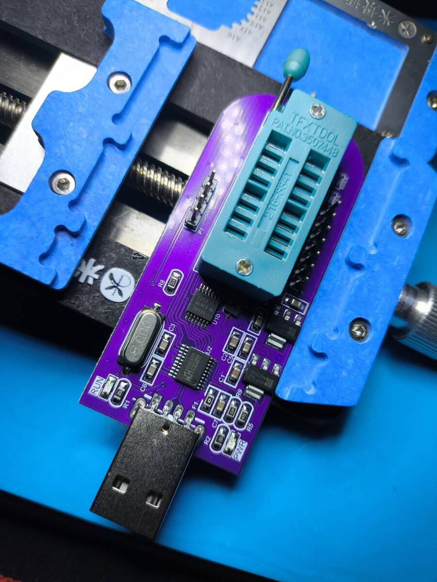 </td>
<td>
Any of the nine supported programmers will do. The one above is a WCH board with a ZIF socket — PWR and RUN on the silkscreen are the power and activity lamps.
Asprogrammer PN drives the CH347 and CH341A through WCH's own DLLs, so the same driver package covers both.
Seat the chip with pin 1 at the lever end of the socket and close the lever before plugging in.
</td> </tr> </table>
- Install the CH347 driver from
drivers/CH347T-Driver/— the CH341PAR package behindwch.cn 2.6.2025.4, confirmed working with this board. - Plug the programmer in. Windows should show USB HighSpeed-SPI/I2C… CH347T with no warning icon.
- Download
AsprogrammerPN-<version>.zipand unpack it.AsprogrammerPN.exeruns from the folder — no installer.
Usage
The toolbar across the top is the safe order to work in, left to right.
Reading a chip
| Step | What to check | |
|---|---|---|
| 1 | Set the target voltage | Target voltage on the left. Auto matches the chip once one is selected; otherwise pin it yourself |
| 2 | Detect chip | Chip profile fills in and the Chip lamp turns green |
| 3 | Read chip | Bytes appear in the hex view; Last operation shows the timing |
| 4 | Save with Ctrl+S |
If detection finds nothing, the log says why — a wrong rail and a loose clip look identical to the chip, and both read back as all FF.
Writing a chip
Smart write is the one to use. It reads the chip first, works out the minimum erase and program needed, shows you that plan, and only proceeds once you accept it. Nothing is written before you have seen what it intends to do.
Every write runs through the same chain, in this order:
| Step | If it fails | |
|---|---|---|
| 1 | Chip identity, read now — not trusted from two minutes ago | An all-FF or all-00 reply is a floating bus, not a chip |
| 2 | Electrical preflight against the chip that actually answered | Refused before the first clock edge |
| 3 | Step order — rail, chip and preflight all still valid | Refused, naming the first missing step |
| 4 | Safe mode check | Refused at the protocol layer — no menu or script can reach past it |
| 5 | Connection stability — three regions read twice and compared | Refused, naming the first differing address |
| 6 | Protection bits | Refused, or asks, depending on what is locked |
| 7 | Trusted backup + .json manifest with SHA-256 |
Write does not start |
| 8 | Erase and program to the previewed plan | |
| 9 | Byte-by-byte verify | Reported with the failing address |
| 10 | Second verify in a fresh USB session | Write is reported as failed, not warned about |
Step 3 is the one that catches mistakes rather than faults. Change the target rail and chip detection is revoked — a chip that answered at 3.3 V is not evidence of a chip at 1.8 V. Load a different image and the preflight that judged the previous one is revoked. Each destructive run consumes its arming, so the next part in the socket goes through the ladder again.
Step 8 closes and reopens the device before re-reading, which catches driver-cached reads and contact that is marginal until something re-initialises. It is not a power-cycle test — no supported programmer can remove target power — and the log says so rather than implying more than it did.
Each backup lands in backup/ as a .bin plus a .json recording the chip, JEDEC ID, capacity, programmer, rail, UTC timestamp and SHA-256. A bare .bin cannot answer any of those questions at the moment you need them answered.
[!WARNING] Set the target voltage to match your chip before erase, write or verify. The board defaults to 1.8 V, so a 3.3 V part simply will not answer until you raise it — that is the safe failure, and it is deliberate.
[!TIP] Working on an unknown part, or a customer's board? Turn on read-only safe mode (Options, or
--safe). It removes the ability to change the chip at the protocol layer, so nothing — no button, no script, no mistake in any of the checks above — can erase, write, unlock or touch a status register.
Reading the status strip
The four panels under the toolbar answer "why is this not working" without digging in the log:
- Connection — which programmer is actually attached
- Interface / clock — bus and SPI clock. A clip lead or long cable often cannot hold 60 MHz; a bus that cannot keep up reads back all
FF, exactly like an empty socket. Rather than guessing, run Auto tune clock and let it find the boundary - Chip profile — the selected part and whether its ID has been confirmed
- Last operation — result and elapsed time
Keyboard
F5 detect · Ctrl+O open · Esc cancel · F1 console
Command line
The executables share lower-level programming engines but expose different interfaces:
| Executable | Scope |
|---|---|
AsprogrammerPN.exe |
Windows application with command-line access to the GUI's chip catalogue and programmer backends, JSON reporting, and authenticated production jobs |
AsprogrammerPNCLI.exe (Windows), AsprogrammerPNCLI (Linux) |
LCL-free CLI for CH347 over libusb: detect, read, Smart Write preview, gated Smart Write, offline image scan and SFDP decode |
Run the selected executable with --help; switches are not interchangeable.
Headless destructive operations remain gated pending live validation. See
headless commands and validation requirements.
The following JSON example, --preflight option and exit-code table apply to
AsprogrammerPN.exe. Its --json option emits one versioned line:
{"schema_version":1,"action":"detect","ok":true,"result":"ok",
 "programmer":"CH347","chip":"W25Q64FW","jedec_id":"EF6017","size":8388608,
 "requested_mv":1800,"measured_mv":null,"target_current_ua":null,
 "external_power_detected":null,"signal_mv":1800,"signal_measured":false}
Values the hardware cannot observe are null, never 0 — a consumer reading "measured_mv":0 as a measurement of zero volts would be making exactly the mistake this whole design exists to prevent. external_power_detected is three-valued for the same reason: false means no external voltage is present, null means this programmer cannot see external voltage, and merging those is how a chip gets written while a motherboard backfeeds its rail.
--preflight reports the rail and whether a destructive operation would be allowed, without touching the bus.
Exit codes distinguish the cases where your next action differs:
0 ok |
1 failed |
2 usage |
3 no programmer |
4 programmer lost |
5 no chip answered |
6 chip mismatch |
7 voltage refused |
8 connection unstable |
9 chip locked |
10 file size mismatch |
11 verify failed |
12 file error |
13 cancelled |
Lab Tools
Lab Tools —
I2C bus scanner·SPI console·UART terminal
Bench instruments, kept in their own menu so the flash programmer's screen stays as simple as its job.
| Tool | What it does |
|---|---|
| I²C bus scanner | Probes 0x08–0x77 and reports what acknowledges. It never touches the reserved ranges: 0000 xxx contains the general call address that every device on the bus obeys, so a scan that includes it is issuing commands rather than asking questions |
| SPI console | Raw command bytes in, hex dump out. A malformed token refuses the whole line rather than being skipped — on a flash chip the difference between 20 and 60 is one sector versus the entire part |
| UART terminal | Straight to a COM port, not through the programmer, so it works with anything plugged in |
The SPI console bypasses every guard in the program and says so. The one it cannot bypass is read-only safe mode, because that latch sits on the opcodes rather than on the buttons.
Hardware
The board is a commercial CH347Ⅱ V2.13, so hardware/ is reverse engineering rather than design output — which is exactly why it is written down, because the software refuses operations on the strength of claims about how this board behaves. hardware/pinout.md tags every claim with how it was established, and one is still marked UNVERIFIED.
vendor-manifest.json records every third-party binary with its SHA-256, licence and origin. Entries marked unrecorded have known bytes and an unknown source; no URL has been invented to fill the gap.
Building
On Windows, use 32-bit Lazarus with FPC 3.2.2
(CI uses Lazarus 4.8). The script defaults to C:\lazarus32; pass
-Lazarus "C:\path\to\lazarus" for another installation.
powershell -ExecutionPolicy Bypass -File tools\build.ps1
powershell -ExecutionPolicy Bypass -File tools\test_desktop.ps1
The build runs the hardware-free suites and builds the Windows application.
The second command runs the desktop simulator smoke test. Add -Release to
tools\build.ps1 to assemble release\AsprogrammerPN-<version>.zip with its
runtime DLLs and data files.
On Debian/Ubuntu, install fp-compiler, fp-units-fcl, and the system OpenSSL
libcrypto runtime, then run:
./tools/build.shThe Linux script runs the hardware-free suites and compile-checks the headless CLI; it does not build the Windows GUI or produce a Linux release package. Running the headless CLI against CH347 hardware also requires libusb 1.0. See testing instructions and headless build and usage.
Changelog
Every release tells its story in CHANGELOG.md — what was wrong, why it mattered, and what the fix protects. Binaries with checksums are on the releases page; CI rebuilds, re-tests and packages every tagged release from scratch before it is published.
Credits
Asprogrammer PN is written by Patnawa.
The safety architecture is this project's own work: the electrical preflight and target-rail reporting, the session admission ladder, clock auto-tuning, the connection-stability gate, read-only safe mode, the erase-geometry builder, the write-admission rule, the machine-facing JSON and exit-code contract, CH347 voltage control, the production job and evidence chain, and the Lab Tools — with the test suite that holds all of it in place.
It began as a fork of AsProgrammer by nofeletru. The SPI, I²C and MicroWire protocol units, several hardware backends, the script engine and the chip catalogue descend from that work and are used under its MIT licence.
Components carrying their own separate licences — MPHexEditor, Ararat Synapse, FTDI D2XX, libusb, and the flashrom chip data — are listed in THIRD_PARTY_NOTICES.md.
Released under the MIT licence.
Built for people who would rather read a datasheet than replace a chip.