

Lazarus on Raspberry Pi/zh CN: what changed
Revision 0 to 1. Removed lines have a minus sign; added lines have a plus sign.
Title: Lazarus on Raspberry Pi/zh CN
| Old | New | Line | |
|---|---|---|---|
| 1 | + | 树莓派上的Lazarus | |
| 2 | + | ||
| 3 | + | <img src="Lazarus_on_Raspberry_Pi_Raspian_Wheezy_version_2012-10-28.png" title="Lazarus on Raspbian Wheezy" width="200" alt="Lazarus on Raspbian Wheezy" /> *(Raspberry Pi only)* | |
| 4 | + | ||
| 5 | + | Raspberry Pi(数莓派)是一个信用卡大小的单板计算机。它由英国的Raspberry Pi基金为了激励在学校的计算机基础科学教学发起的。Raspberry Pis也可以用来作为媒体服务器以及其他用途机器人、控制工程等多种用途。 Raspberry Pi基金会推荐[[Raspbian]] Wheezy作为标准的操作系统。大家可以选择在RPI运行RISC OS、各种Linux发行版以及[[Android]]等操作系统。 Lazarus可以在原生的Raspbian操作系统下运行。 | |
| 6 | + | ||
| 7 | + | ## 安装与编译器Lazarus | |
| 8 | + | ||
| 9 | + | ### 在 Raspbian上简单安装 | |
| 10 | + | ||
| 11 | + | #### Raspberry Pi 1 | |
| 12 | + | ||
| 13 | + | 在 Raspbian OS上,安装Lazarus与 Free Pascal很容易。打开命令行窗口输入下面的指令: | |
| 14 | + | ||
| 15 | + | ``` bash | |
| 16 | + | sudo apt-get update | |
| 17 | + | sudo apt-get upgrade | |
| 18 | + | sudo apt-get install fpc | |
| 19 | + | sudo apt-get install lazarus | |
| 20 | + | ``` | |
| 21 | + | ||
| 22 | + | 这里安装的是为Raspberry Pi预编译的稳定版FPC与Lazarus 。当然,需要有网络连接。安装过程大概需要30分钟,这个过程是自动完成等的。安装完成以后,你就可以从LXDE的开始菜单的“Programming”启动Lazarus了。 | |
| 23 | + | ||
| 24 | + | Install Lazarus Rasbian Part1 en.png\|安装步骤 1 Install Lazarus Rasbian Part2 en.png\|安装步骤 2 Install Lazarus Rasbian Part3 en.png\|安装步骤 3 Install Lazarus Rasbian Part4 en.png\|安装步骤 4 | |
| 25 | + | ||
| 26 | + | 如果你需要一个新的版本,或者抱怨Lazarus 的问题, [点击](http://www.raspberrypi.org/forums/viewtopic.php?f=34&t=88145). | |
| 27 | + | ||
| 28 | + | #### Raspberry Pi 2 | |
| 29 | + | ||
| 30 | + | 自2015六月起,普通的“out of the box”安装方法也适用于安装树莓派2的B型。但是安装时获得的版本是相当旧的。想要获得新版FPC和Lazarus请看链接 [相关文章](http://www.tweaking4all.com/hardware/raspberry-pi/install-lazarus-pascal-on-raspberry-pi-2/). | |
| 31 | + | ||
| 32 | + | <File:Lazarus> 0 9 30 4 on RPi 2.png\|Lazarus "out of the box" on Raspberry Pi 2 | |
| 33 | + | ||
| 34 | + | ### 从Windows 对Raspberry Pi的交叉编译 | |
| 35 | + | ||
| 36 | + | 1\. 使用 fpcup | |
| 37 | + | ||
| 38 | + | 使用fpcup是实现交叉编译的一种方法,输入下面的指令: [[fpcup|fpcup#Linux_ARM_cross_compiler]] | |
| 39 | + | ||
| 40 | + | 2\. 使用脚本 | |
| 41 | + | ||
| 42 | + | 可以使用手动批处理文件,按照以下步骤。 | |
| 43 | + | ||
| 44 | + | 2.1 先决条件 | |
| 45 | + | ||
| 46 | + | `FPC 2.7.1或更高的安装源代码`\ | |
| 47 | + | `下载并安装Windows版本的Linaro binutils for linux gnueabihf到%FPCPATH%/bin/win32-armhf-linux `[`1`](https://launchpad.net/linaro-toolchain-binaries/trunk/2013.10/+download/gcc-linaro-arm-linux-gnueabihf-4.8-2013.10_win32.zip) | |
| 48 | + | ||
| 49 | + | 2.2 创建脚本(需要匹配实际路径) | |
| 50 | + | ||
| 51 | + | ``` bat | |
| 52 | + | set PATH=C:\pp\bin\i386-win32;%PATH%; | |
| 53 | + | set FPCMAKEPATH=C:/pp | |
| 54 | + | set FPCPATH=C:/pp | |
| 55 | + | set OUTPATH=C:/pp271 | |
| 56 | + | %FPCMAKEPATH%/bin/i386-win32/make distclean OS_TARGET=linux CPU_TARGET=arm CROSSBINDIR=%FPCPATH%/bin/win32-armhf-linux CROSSOPT="-CpARMV6 -CfVFPV2 -OoFASTMATH" FPC=%FPCPATH%/bin/i386-win32/ppc386.exe | |
| 57 | + | ||
| 58 | + | %FPCMAKEPATH%/bin/i386-win32/make all OS_TARGET=linux CPU_TARGET=arm CROSSBINDIR=%FPCPATH%/bin/win32-armhf-linux CROSSOPT="-CpARMV6 -CfVFPV2 -OoFASTMATH" FPC=%FPCPATH%/bin/i386-win32/ppc386.exe | |
| 59 | + | if errorlevel 1 goto quit | |
| 60 | + | %FPCMAKEPATH%/bin/i386-win32/make crossinstall CROSSBINDIR=%FPCPATH%/bin/win32-armhf-linux CROSSOPT="-CpARMV6 -CfVFPV2 -OoFASTMATH" OS_TARGET=linux CPU_TARGET=arm FPC=%FPCPATH%/bin/i386-win32/ppc386.exe INSTALL_BASEDIR=%OUTPATH% | |
| 61 | + | ||
| 62 | + | :quit | |
| 63 | + | pause | |
| 64 | + | ``` | |
| 65 | + | ||
| 66 | + | 使用生成的ppcrossarm.exe和 ARM RTL,你可以创建跨平台的Lazarus工程,生成Raspberry Pi和其他armhf设备的应用程序。 注意,这里不包括所有Window 库。 | |
| 67 | + | ||
| 68 | + | ### 编译源代码 | |
| 69 | + | ||
| 70 | + | 如果你想要从Subversion编译Lazarus源代码。请看 \[<http://www.michellcomputing.co.uk/blog/?p=72>: Michell Computing: Lazarus on the Raspberry Pi\] | |
| 71 | + | ||
| 72 | + | <File:Start> Menu with Lazarus en.png\|How to start Lazarus in Raspbian Wheezy <File:Lazarus> on Raspberry Pi.jpg\|Lazarus on Raspberry Pi <File:rpi> gpio pins.png\|Numbering of GPIO pins | |
| 73 | + | ||
| 74 | + | 用Gentoo(及其他版本)在Raspberry上编译源码 | |
| 75 | + | ||
| 76 | + | - Gentoo是一个基于Linux的自由操作系统 | |
| 77 | + | ||
| 78 | + | ------------------------------------------------------------------------ | |
| 79 | + | ||
| 80 | + | 如果你想安装最新版的FPC及附件,或者是集成FPC编译器:请阅读下面的指南 这是关于Gentoo的例子,本指南适用其他版本:[[Install fpc on Raspberry with Gentoo]] | |
| 81 | + | ||
| 82 | + | ## 访问外部硬件 | |
| 83 | + | ||
| 84 | + | <figure> | |
| 85 | + | <img src="rpi_pinout_all_50.png" title="Raspberry Pi 外部连接引脚" width="300" /> | |
| 86 | + | <figcaption>Raspberry Pi 外部连接引脚</figcaption> | |
| 87 | + | </figure> | |
| 88 | + | ||
| 89 | + | Raspberry Pi的发展的目标之一是方便轻松地访问外部设备,如传感器和控制器。Lazarus有五种方法来访问I/O设备: | |
| 90 | + | ||
| 91 | + | 1. [[Lazarus on Raspberry Pi|原生代码直接访问]],使用[[BaseUnix]]单元 | |
| 92 | + | 2. 通过 [[Lazarus on Raspberry Pi|封装外壳调用]] | |
| 93 | + | 3. 通过 [[Lazarus on Raspberry Pi|wiringPi 库]]. | |
| 94 | + | 4. 使用单元 [[Lazarus on Raspberry Pi|rpi_hal]]. | |
| 95 | + | 5. 使用单元 [[Lazarus on Raspberry Pi|PiGpio]]. | |
| 96 | + | 6. 通过 [PascalIO](https://github.com/SAmeis/pascalio) 库访问. | |
| 97 | + | ||
| 98 | + | ### 1. 原生代码直接访问 | |
| 99 | + | ||
| 100 | + | 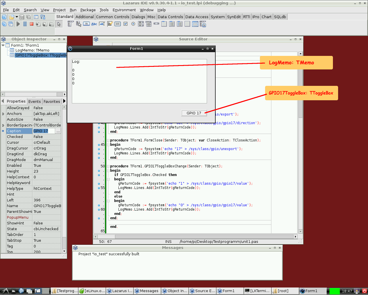 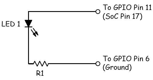 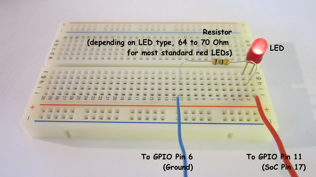 | |
| 101 | + | ||
| 102 | + | 这种访问外部硬件的方法,不需要额外的库。唯一的要求是baseunix库,这是Free Pascal的RTL部分。 | |
| 103 | + | ||
| 104 | + | #### 通过GPIO端口控制开关 | |
| 105 | + | ||
| 106 | + | 下面将演示一个简单程序。控制GPIO的17号引脚的电压,可以用来控制LED、晶体管或继电器。 程序包含*GPIO17ToggleBox*的实例[[doc:lcl/stdctrls/ttogglebox.html|ToggleBox]]和日志返回*LogMemo*类的实例[[doc:lcl/stdctrls/tmemo.html|TMemo]]。 | |
| 107 | + | ||
| 108 | + | 例如,一个LED的阳极连接到引脚11上(BCM2835 SoC对应的GPIO为17)和LED的阴极通过一个68欧姆的电阻连接引脚6(GND)。随后,LED会随着应用程序的toggle box切换点亮和熄灭。 | |
| 109 | + | ||
| 110 | + | 该代码需要root权限运行,即从root帐号(不推荐)运行或通过“*su*'。 | |
| 111 | + | ||
| 112 | + | *控制单元:* | |
| 113 | + | ||
| 114 | + | ``` pascal | |
| 115 | + | unit Unit1; | |
| 116 | + | ||
| 117 | + | {Demo application for GPIO on Raspberry Pi} | |
| 118 | + | {Inspired by the Python input/output demo application by Gareth Halfacree} | |
| 119 | + | {written for the Raspberry Pi User Guide, ISBN 978-1-118-46446-5} | |
| 120 | + | ||
| 121 | + | {$mode objfpc}{$H+} | |
| 122 | + | ||
| 123 | + | interface | |
| 124 | + | ||
| 125 | + | uses | |
| 126 | + | Classes, SysUtils, FileUtil, Forms, Controls, Graphics, Dialogs, StdCtrls, | |
| 127 | + | Unix, BaseUnix; | |
| 128 | + | ||
| 129 | + | type | |
| 130 | + | ||
| 131 | + | { TForm1 } | |
| 132 | + | ||
| 133 | + | TForm1 = class(TForm) | |
| 134 | + | LogMemo: TMemo; | |
| 135 | + | GPIO17ToggleBox: TToggleBox; | |
| 136 | + | procedure FormActivate(Sender: TObject); | |
| 137 | + | procedure FormClose(Sender: TObject; var CloseAction: TCloseAction); | |
| 138 | + | procedure GPIO17ToggleBoxChange(Sender: TObject); | |
| 139 | + | private | |
| 140 | + | { private declarations } | |
| 141 | + | public | |
| 142 | + | { public declarations } | |
| 143 | + | end; | |
| 144 | + | ||
| 145 | + | const | |
| 146 | + | PIN_17: PChar = '17'; | |
| 147 | + | PIN_ON: PChar = '1'; | |
| 148 | + | PIN_OFF: PChar = '0'; | |
| 149 | + | OUT_DIRECTION: PChar = 'out'; | |
| 150 | + | ||
| 151 | + | var | |
| 152 | + | Form1: TForm1; | |
| 153 | + | gReturnCode: longint; {stores the result of the IO operation} | |
| 154 | + | ||
| 155 | + | implementation | |
| 156 | + | ||
| 157 | + | {$R *.lfm} | |
| 158 | + | ||
| 159 | + | { TForm1 } | |
| 160 | + | ||
| 161 | + | procedure TForm1.FormActivate(Sender: TObject); | |
| 162 | + | var | |
| 163 | + | fileDesc: integer; | |
| 164 | + | begin | |
| 165 | + | { Prepare SoC pin 17 (pin 11 on GPIO port) for access: } | |
| 166 | + | try | |
| 167 | + | fileDesc := fpopen('/sys/class/gpio/export', O_WrOnly); | |
| 168 | + | gReturnCode := fpwrite(fileDesc, PIN_17[0], 2); | |
| 169 | + | LogMemo.Lines.Add(IntToStr(gReturnCode)); | |
| 170 | + | finally | |
| 171 | + | gReturnCode := fpclose(fileDesc); | |
| 172 | + | LogMemo.Lines.Add(IntToStr(gReturnCode)); | |
| 173 | + | end; | |
| 174 | + | { Set SoC pin 17 as output: } | |
| 175 | + | try | |
| 176 | + | fileDesc := fpopen('/sys/class/gpio/gpio17/direction', O_WrOnly); | |
| 177 | + | gReturnCode := fpwrite(fileDesc, OUT_DIRECTION[0], 3); | |
| 178 | + | LogMemo.Lines.Add(IntToStr(gReturnCode)); | |
| 179 | + | finally | |
| 180 | + | gReturnCode := fpclose(fileDesc); | |
| 181 | + | LogMemo.Lines.Add(IntToStr(gReturnCode)); | |
| 182 | + | end; | |
| 183 | + | end; | |
| 184 | + | ||
| 185 | + | procedure TForm1.FormClose(Sender: TObject; var CloseAction: TCloseAction); | |
| 186 | + | var | |
| 187 | + | fileDesc: integer; | |
| 188 | + | begin | |
| 189 | + | { Free SoC pin 17: } | |
| 190 | + | try | |
| 191 | + | fileDesc := fpopen('/sys/class/gpio/unexport', O_WrOnly); | |
| 192 | + | gReturnCode := fpwrite(fileDesc, PIN_17[0], 2); | |
| 193 | + | LogMemo.Lines.Add(IntToStr(gReturnCode)); | |
| 194 | + | finally | |
| 195 | + | gReturnCode := fpclose(fileDesc); | |
| 196 | + | LogMemo.Lines.Add(IntToStr(gReturnCode)); | |
| 197 | + | end; | |
| 198 | + | end; | |
| 199 | + | ||
| 200 | + | procedure TForm1.GPIO17ToggleBoxChange(Sender: TObject); | |
| 201 | + | var | |
| 202 | + | fileDesc: integer; | |
| 203 | + | begin | |
| 204 | + | if GPIO17ToggleBox.Checked then | |
| 205 | + | begin | |
| 206 | + | { Swith SoC pin 17 on: } | |
| 207 | + | try | |
| 208 | + | fileDesc := fpopen('/sys/class/gpio/gpio17/value', O_WrOnly); | |
| 209 | + | gReturnCode := fpwrite(fileDesc, PIN_ON[0], 1); | |
| 210 | + | LogMemo.Lines.Add(IntToStr(gReturnCode)); | |
| 211 | + | finally | |
| 212 | + | gReturnCode := fpclose(fileDesc); | |
| 213 | + | LogMemo.Lines.Add(IntToStr(gReturnCode)); | |
| 214 | + | end; | |
| 215 | + | end | |
| 216 | + | else | |
| 217 | + | begin | |
| 218 | + | { Switch SoC pin 17 off: } | |
| 219 | + | try | |
| 220 | + | fileDesc := fpopen('/sys/class/gpio/gpio17/value', O_WrOnly); | |
| 221 | + | gReturnCode := fpwrite(fileDesc, PIN_OFF[0], 1); | |
| 222 | + | LogMemo.Lines.Add(IntToStr(gReturnCode)); | |
| 223 | + | finally | |
| 224 | + | gReturnCode := fpclose(fileDesc); | |
| 225 | + | LogMemo.Lines.Add(IntToStr(gReturnCode)); | |
| 226 | + | end; | |
| 227 | + | end; | |
| 228 | + | end; | |
| 229 | + | ||
| 230 | + | end. | |
| 231 | + | ``` | |
| 232 | + | ||
| 233 | + | *Main program:* | |
| 234 | + | ||
| 235 | + | ``` pascal | |
| 236 | + | program io_test; | |
| 237 | + | ||
| 238 | + | {$mode objfpc}{$H+} | |
| 239 | + | ||
| 240 | + | uses | |
| 241 | + | {$IFDEF UNIX}{$IFDEF UseCThreads} | |
| 242 | + | cthreads, | |
| 243 | + | {$ENDIF}{$ENDIF} | |
| 244 | + | Interfaces, // this includes the LCL widgetset | |
| 245 | + | Forms, Unit1 | |
| 246 | + | { you can add units after this }; | |
| 247 | + | ||
| 248 | + | {$R *.res} | |
| 249 | + | ||
| 250 | + | begin | |
| 251 | + | Application.Initialize; | |
| 252 | + | Application.CreateForm(TForm1, Form1); | |
| 253 | + | Application.Run; | |
| 254 | + | end. | |
| 255 | + | ``` | |
| 256 | + | ||
| 257 | + | #### 读取引脚的状态 | |
| 258 | + | ||
| 259 | + | 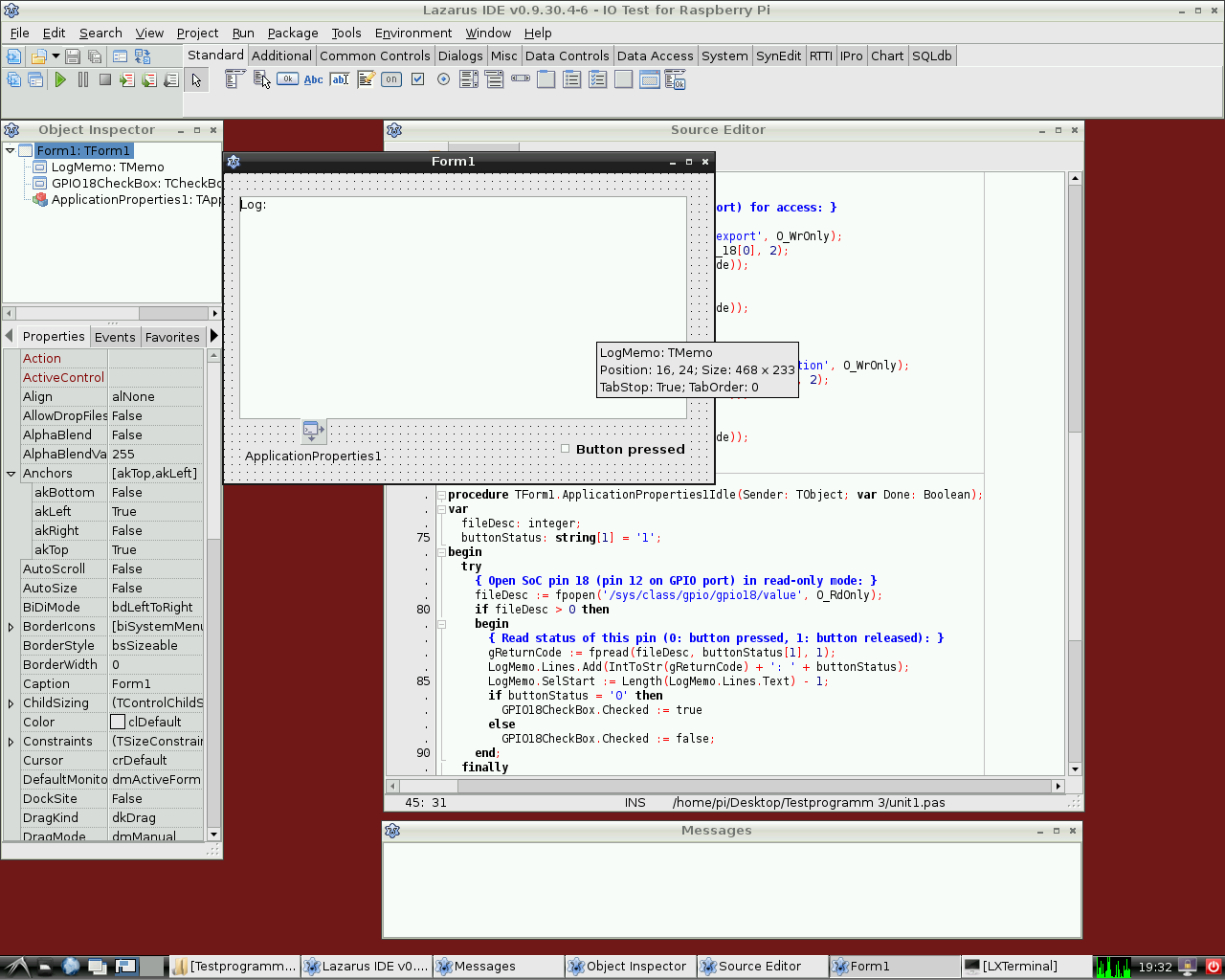 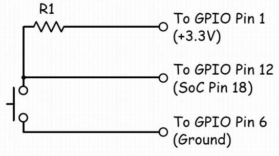 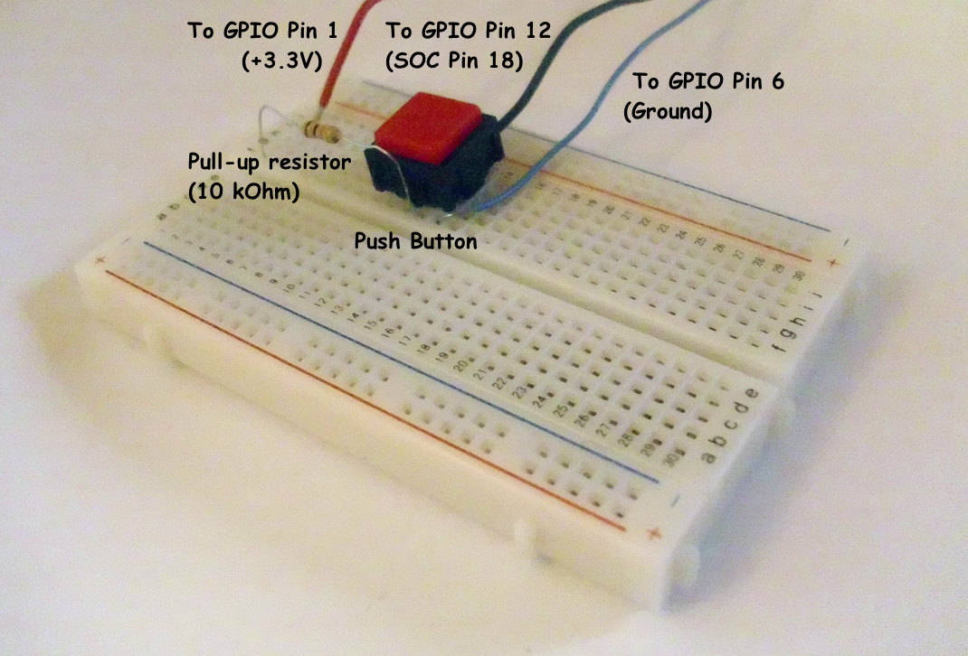 | |
| 260 | + | ||
| 261 | + | 当然也可以从GPIO端口读取一个开关的状态。 | |
| 262 | + | ||
| 263 | + | 下面的简单例子非常类似于前一个例子。使用GPIO的18号引脚,控制二进制设备如开关输入,晶体管或继电器。这个程序包含一个名称为[[doc:lcl/stdctrls/tcheckbox.html|CheckBox]]的*GPIO18CheckBox* 与*LogMemo*的实例[[doc:lcl/stdctrls/tmemo.html|TMemo]]日志返回代码。 | |
| 264 | + | ||
| 265 | + | 在实例中,第12引脚的一端连接一个按钮,按钮的一端(对应的GPIO引脚18的BCM2835 SoC)通过一个10欧姆的上拉电阻和引脚1连接(+3.3 V,看接线图)。按钮的另一端连接6号引脚(GND)。按钮的开关状态对应和程序中复选框的打开或关闭状态对应。 | |
| 266 | + | ||
| 267 | + | 注意,当按钮释放时18脚的电位为高(由通过上拉电阻连接到引脚1),当按钮压下时电压为低(因为在这种情况下,引脚18是通过开关连接到GND)。因此,按钮按下时GPIO引脚信号为0,当释放时信号为1。 | |
| 268 | + | ||
| 269 | + | 这个程序同样需要root权限 | |
| 270 | + | ||
| 271 | + | *控制单元:* | |
| 272 | + | ||
| 273 | + | ``` pascal | |
| 274 | + | unit Unit1; | |
| 275 | + | ||
| 276 | + | {Demo application for GPIO on Raspberry Pi} | |
| 277 | + | {Inspired by the Python input/output demo application by Gareth Halfacree} | |
| 278 | + | {written for the Raspberry Pi User Guide, ISBN 978-1-118-46446-5} | |
| 279 | + | ||
| 280 | + | {This application reads the status of a push-button} | |
| 281 | + | ||
| 282 | + | {$mode objfpc}{$H+} | |
| 283 | + | ||
| 284 | + | interface | |
| 285 | + | ||
| 286 | + | uses | |
| 287 | + | Classes, SysUtils, FileUtil, Forms, Controls, Graphics, Dialogs, StdCtrls, | |
| 288 | + | ButtonPanel, Unix, BaseUnix; | |
| 289 | + | ||
| 290 | + | type | |
| 291 | + | ||
| 292 | + | { TForm1 } | |
| 293 | + | ||
| 294 | + | TForm1 = class(TForm) | |
| 295 | + | ApplicationProperties1: TApplicationProperties; | |
| 296 | + | GPIO18CheckBox: TCheckBox; | |
| 297 | + | LogMemo: TMemo; | |
| 298 | + | procedure ApplicationProperties1Idle(Sender: TObject; var Done: Boolean); | |
| 299 | + | procedure FormActivate(Sender: TObject); | |
| 300 | + | procedure FormClose(Sender: TObject; var CloseAction: TCloseAction); | |
| 301 | + | private | |
| 302 | + | { private declarations } | |
| 303 | + | public | |
| 304 | + | { public declarations } | |
| 305 | + | end; | |
| 306 | + | ||
| 307 | + | const | |
| 308 | + | PIN_18: PChar = '18'; | |
| 309 | + | IN_DIRECTION: PChar = 'in'; | |
| 310 | + | ||
| 311 | + | var | |
| 312 | + | Form1: TForm1; | |
| 313 | + | gReturnCode: longint; {stores the result of the IO operation} | |
| 314 | + | ||
| 315 | + | implementation | |
| 316 | + | ||
| 317 | + | {$R *.lfm} | |
| 318 | + | ||
| 319 | + | { TForm1 } | |
| 320 | + | ||
| 321 | + | procedure TForm1.FormActivate(Sender: TObject); | |
| 322 | + | var | |
| 323 | + | fileDesc: integer; | |
| 324 | + | begin | |
| 325 | + | { Prepare SoC pin 18 (pin 12 on GPIO port) for access: } | |
| 326 | + | try | |
| 327 | + | fileDesc := fpopen('/sys/class/gpio/export', O_WrOnly); | |
| 328 | + | gReturnCode := fpwrite(fileDesc, PIN_18[0], 2); | |
| 329 | + | LogMemo.Lines.Add(IntToStr(gReturnCode)); | |
| 330 | + | finally | |
| 331 | + | gReturnCode := fpclose(fileDesc); | |
| 332 | + | LogMemo.Lines.Add(IntToStr(gReturnCode)); | |
| 333 | + | end; | |
| 334 | + | { Set SoC pin 18 as input: } | |
| 335 | + | try | |
| 336 | + | fileDesc := fpopen('/sys/class/gpio/gpio18/direction', O_WrOnly); | |
| 337 | + | gReturnCode := fpwrite(fileDesc, IN_DIRECTION[0], 2); | |
| 338 | + | LogMemo.Lines.Add(IntToStr(gReturnCode)); | |
| 339 | + | finally | |
| 340 | + | gReturnCode := fpclose(fileDesc); | |
| 341 | + | LogMemo.Lines.Add(IntToStr(gReturnCode)); | |
| 342 | + | end; | |
| 343 | + | end; | |
| 344 | + | ||
| 345 | + | procedure TForm1.ApplicationProperties1Idle(Sender: TObject; var Done: Boolean); | |
| 346 | + | var | |
| 347 | + | fileDesc: integer; | |
| 348 | + | buttonStatus: string[1] = '1'; | |
| 349 | + | begin | |
| 350 | + | try | |
| 351 | + | { Open SoC pin 18 (pin 12 on GPIO port) in read-only mode: } | |
| 352 | + | fileDesc := fpopen('/sys/class/gpio/gpio18/value', O_RdOnly); | |
| 353 | + | if fileDesc > 0 then | |
| 354 | + | begin | |
| 355 | + | { Read status of this pin (0: button pressed, 1: button released): } | |
| 356 | + | gReturnCode := fpread(fileDesc, buttonStatus[1], 1); | |
| 357 | + | LogMemo.Lines.Add(IntToStr(gReturnCode) + ': ' + buttonStatus); | |
| 358 | + | LogMemo.SelStart := Length(LogMemo.Lines.Text) - 1; | |
| 359 | + | if buttonStatus = '0' then | |
| 360 | + | GPIO18CheckBox.Checked := true | |
| 361 | + | else | |
| 362 | + | GPIO18CheckBox.Checked := false; | |
| 363 | + | end; | |
| 364 | + | finally | |
| 365 | + | { Close SoC pin 18 (pin 12 on GPIO port) } | |
| 366 | + | gReturnCode := fpclose(fileDesc); | |
| 367 | + | LogMemo.Lines.Add(IntToStr(gReturnCode)); | |
| 368 | + | LogMemo.SelStart := Length(LogMemo.Lines.Text) - 1; | |
| 369 | + | end; | |
| 370 | + | end; | |
| 371 | + | ||
| 372 | + | procedure TForm1.FormClose(Sender: TObject; var CloseAction: TCloseAction); | |
| 373 | + | var | |
| 374 | + | fileDesc: integer; | |
| 375 | + | begin | |
| 376 | + | { Free SoC pin 18: } | |
| 377 | + | try | |
| 378 | + | fileDesc := fpopen('/sys/class/gpio/unexport', O_WrOnly); | |
| 379 | + | gReturnCode := fpwrite(fileDesc, PIN_18[0], 2); | |
| 380 | + | LogMemo.Lines.Add(IntToStr(gReturnCode)); | |
| 381 | + | finally | |
| 382 | + | gReturnCode := fpclose(fileDesc); | |
| 383 | + | LogMemo.Lines.Add(IntToStr(gReturnCode)); | |
| 384 | + | end; | |
| 385 | + | end; | |
| 386 | + | ||
| 387 | + | end. | |
| 388 | + | ``` | |
| 389 | + | ||
| 390 | + | 上面的例子主程序是相同的,。 | |
| 391 | + | ||
| 392 | + | ### 2. 通过封装的外壳访问硬件 | |
| 393 | + | ||
| 394 | + | 访问硬件的另一种方法是通过封装终端命令。这是通过使用[[Executing External Programs|fpsystem]]功能。这种方法可以访问baseunix单元不支持的功能。下面的代码实现了一个具有相同功能的程序,该程序是从上面的第一个清单所产生的。 | |
| 395 | + | ||
| 396 | + | *控制单元:* | |
| 397 | + | ||
| 398 | + | ``` pascal | |
| 399 | + | unit Unit1; | |
| 400 | + | ||
| 401 | + | {Demo application for GPIO on Raspberry Pi} | |
| 402 | + | {Inspired by the Python input/output demo application by Gareth Halfacree} | |
| 403 | + | {written for the Raspberry Pi User Guide, ISBN 978-1-118-46446-5} | |
| 404 | + | ||
| 405 | + | {$mode objfpc}{$H+} | |
| 406 | + | ||
| 407 | + | interface | |
| 408 | + | ||
| 409 | + | uses | |
| 410 | + | Classes, SysUtils, FileUtil, Forms, Controls, Graphics, Dialogs, StdCtrls, Unix; | |
| 411 | + | ||
| 412 | + | type | |
| 413 | + | ||
| 414 | + | { TForm1 } | |
| 415 | + | ||
| 416 | + | TForm1 = class(TForm) | |
| 417 | + | LogMemo: TMemo; | |
| 418 | + | GPIO17ToggleBox: TToggleBox; | |
| 419 | + | procedure FormActivate(Sender: TObject); | |
| 420 | + | procedure FormClose(Sender: TObject; var CloseAction: TCloseAction); | |
| 421 | + | procedure GPIO17ToggleBoxChange(Sender: TObject); | |
| 422 | + | private | |
| 423 | + | { private declarations } | |
| 424 | + | public | |
| 425 | + | { public declarations } | |
| 426 | + | end; | |
| 427 | + | ||
| 428 | + | var | |
| 429 | + | Form1: TForm1; | |
| 430 | + | gReturnCode: longint; {stores the result of the IO operation} | |
| 431 | + | ||
| 432 | + | implementation | |
| 433 | + | ||
| 434 | + | {$R *.lfm} | |
| 435 | + | ||
| 436 | + | { TForm1 } | |
| 437 | + | ||
| 438 | + | procedure TForm1.FormActivate(Sender: TObject); | |
| 439 | + | begin | |
| 440 | + | { Prepare SoC pin 17 (pin 11 on GPIO port) for access: } | |
| 441 | + | gReturnCode := fpsystem('echo "17" > /sys/class/gpio/export'); | |
| 442 | + | LogMemo.Lines.Add(IntToStr(gReturnCode)); | |
| 443 | + | { Set SoC pin 17 as output: } | |
| 444 | + | gReturnCode := fpsystem('echo "out" > /sys/class/gpio/gpio17/direction'); | |
| 445 | + | LogMemo.Lines.Add(IntToStr(gReturnCode)); | |
| 446 | + | end; | |
| 447 | + | ||
| 448 | + | procedure TForm1.FormClose(Sender: TObject; var CloseAction: TCloseAction); | |
| 449 | + | begin | |
| 450 | + | { Free SoC pin 17: } | |
| 451 | + | gReturnCode := fpsystem('echo "17" > /sys/class/gpio/unexport'); | |
| 452 | + | LogMemo.Lines.Add(IntToStr(gReturnCode)); | |
| 453 | + | end; | |
| 454 | + | ||
| 455 | + | procedure TForm1.GPIO17ToggleBoxChange(Sender: TObject); | |
| 456 | + | begin | |
| 457 | + | if GPIO17ToggleBox.Checked then | |
| 458 | + | begin | |
| 459 | + | { Swith SoC pin 17 on: } | |
| 460 | + | gReturnCode := fpsystem('echo "1" > /sys/class/gpio/gpio17/value'); | |
| 461 | + | LogMemo.Lines.Add(IntToStr(gReturnCode)); | |
| 462 | + | end | |
| 463 | + | else | |
| 464 | + | begin | |
| 465 | + | { Switch SoC pin 17 off: } | |
| 466 | + | gReturnCode := fpsystem('echo "0" > /sys/class/gpio/gpio17/value'); | |
| 467 | + | LogMemo.Lines.Add(IntToStr(gReturnCode)); | |
| 468 | + | end; | |
| 469 | + | end; | |
| 470 | + | ||
| 471 | + | end. | |
| 472 | + | ``` | |
| 473 | + | ||
| 474 | + | 主程序与上面的例子相同。这个程序必须用根权限执行。 | |
| 475 | + | ||
| 476 | + | ### 3. wiringPi方法与函数 | |
| 477 | + | ||
| 478 | + | Alex Schaller封装的Gordon Henderson的Arduino兼容wiringpi库,提供了一种类似Arduino电路板的编码方案。 | |
| 479 | + | ||
| 480 | + | **Function wiringPiSetup:longint:** 使用wiringpi引脚编号方案初始化wiringpi系统 | |
| 481 | + | ||
| 482 | + | **Procedure wiringPiGpioMode(mode:longint):** 用Broadcom的GPIO引脚编号方案wiringpi初始化系统。 | |
| 483 | + | ||
| 484 | + | **Procedure pullUpDnControl(pin:longint;** pud:longint): 控制内部GPIO引脚上拉/下拉电阻。 | |
| 485 | + | ||
| 486 | + | **Procedure pinMode(pin:longint; mode:longint):** 设置一个PIN的模式:输入、输出或pwm_output。 | |
| 487 | + | ||
| 488 | + | **Procedure digitalWrite(pin:longint; value:longint):** 设置一个输出位。 | |
| 489 | + | ||
| 490 | + | **Procedure pwmWrite(pin:longint; value:longint):** 设置一个输出PWM(脉宽调制)值,0到1024之间。 | |
| 491 | + | ||
| 492 | + | **Function digitalRead(pin:longint):longint:** 读取一个给定引脚的值,返回1或0。 | |
| 493 | + | ||
| 494 | + | **Procedure delay(howLong:dword):** 等待多少毫秒。 | |
| 495 | + | ||
| 496 | + | **Procedure delayMicroseconds(howLong:dword):** 等待多少微秒。 | |
| 497 | + | ||
| 498 | + | **Function millis:dword:** 返回程序调用wiringpisetup函数花费的毫秒数。 | |
| 499 | + | ||
| 500 | + | ### 4. rpi_hal-hardware抽象库 (GPIO, I2C and SPI 函数与方法) | |
| 501 | + | ||
| 502 | + | 这个单元大约1700行代码,由Stefan Fischer提供,提供程序和函数访问RPI硬件I2C,SPI和GPIO: | |
| 503 | + | ||
| 504 | + | 下面是函数和方法的摘录: | |
| 505 | + | ||
| 506 | + | **procedure gpio_set_pin (pin:longword;highlevel:boolean);** { 设置 RPi GPIO 引脚速率为高或低; 速率 @ 700MHz -\> 0.65MHz } | |
| 507 | + | ||
| 508 | + | **function gpio_get_PIN (pin:longword):boolean;** { 获取 RPi GPIO 引脚等级,当Pin为'1'时返回True,为'0'时返回false; 速率 @ 700MHz -\> 1.17MHz } | |
| 509 | + | ||
| 510 | + | **procedure gpio_set_input (pin:longword);** { 设置 RPi GPIO 引脚为直接输入} | |
| 511 | + | ||
| 512 | + | **procedure gpio_set_output(pin:longword);** { 设置 RPi GPIO 引脚为直接输出 } | |
| 513 | + | ||
| 514 | + | **procedure gpio_set_alt (pin,altfunc:longword);** { 设置 RPi GPIO 引脚为备用功能 0..5 } | |
| 515 | + | ||
| 516 | + | **procedure gpio_set_gppud (mask:longword);** { 设置RPI GPIO拉上/下登记(gppud)} | |
| 517 | + | ||
| 518 | + | ... | |
| 519 | + | ||
| 520 | + | **function rpi_snr :string;** { 信噪比: 0000000012345678 } | |
| 521 | + | ||
| 522 | + | **function rpi_hw :string;** { 处理器类型: BCM2708 } | |
| 523 | + | ||
| 524 | + | **function rpi_proc:string;** { ARMv6-compatible processor rev 7 (v6l) } | |
| 525 | + | ||
| 526 | + | ... | |
| 527 | + | ||
| 528 | + | **function i2c_bus_write(baseadr,reg:word; var <data:databuf_t>; lgt:byte; testnr:integer) : integer;** | |
| 529 | + | ||
| 530 | + | **function i2c_bus_read (baseadr,reg:word; var <data:databuf_t>; lgt:byte; testnr:integer) : integer;** | |
| 531 | + | ||
| 532 | + | **function i2c_string_read(baseadr,reg:word; var <data:databuf_t>; lgt:byte; testnr:integer) : string;** | |
| 533 | + | ||
| 534 | + | **function i2c_string_write(baseadr,reg:word; s:string; testnr:integer) : integer;** | |
| 535 | + | ||
| 536 | + | ... | |
| 537 | + | ||
| 538 | + | **procedure SPI_Write(devnum:byte; reg,data:word);** | |
| 539 | + | ||
| 540 | + | **function SPI_Read(devnum:byte; reg:word) : byte;** | |
| 541 | + | ||
| 542 | + | **procedure SPI_BurstRead2Buffer (devnum,start_reg:byte; xferlen:longword);** | |
| 543 | + | ||
| 544 | + | **procedure SPI_BurstWriteBuffer (devnum,start_reg:byte; xferlen:longword);** { 从缓冲区SPI的地址写入一段字节的内容 } | |
| 545 | + | ||
| 546 | + | ... | |
| 547 | + | ||
| 548 | + | *测试程序 (testrpi.pas):* | |
| 549 | + | ||
| 550 | + | ``` pascal | |
| 551 | + | //Simple Test program, which is using rpi_hal; | |
| 552 | + | ||
| 553 | + | program testrpi; | |
| 554 | + | uses rpi_hal; | |
| 555 | + | begin | |
| 556 | + | writeln('Show CPU-Info, RPI-HW-Info and Registers:'); | |
| 557 | + | rpi_show_all_info; | |
| 558 | + | writeln('Let Status LED Blink. Using GPIO functions:'); | |
| 559 | + | GPIO_PIN_TOGGLE_TEST; | |
| 560 | + | writeln('Test SPI Read function. (piggy back board with installed RFM22B Module is required!)'); | |
| 561 | + | Test_SPI; | |
| 562 | + | end. | |
| 563 | + | ``` | |
| 564 | + | ||
| 565 | + | ### 5. 底层pascal单元 PiGpio(代替wiringpi C语言库的GPIO控制) | |
| 566 | + | ||
| 567 | + | *这个单元 (pigpio.pas[2](https://docs.google.com/file/d/0B-b-5ooIWPvGN1BIcEJzRDgyeUE/edit?usp=sharing)) 270 行代码是由Gabor Szollosi提供的 , 运行速度飞快(例如GPIO引脚输出开关频率达到8MHz) :* | |
| 568 | + | ||
| 569 | + | ``` pascal | |
| 570 | + | unit PiGpio; | |
| 571 | + | { | |
| 572 | + | BCM2835 GPIO Registry Driver, also can use to manipulate cpu other registry areas | |
| 573 | + | ||
| 574 | + | This code is tested only Broadcom bcm2835 cpu, different arm cpus may need different | |
| 575 | + | gpio driver implementation | |
| 576 | + | ||
| 577 | + | 2013 Gabor Szollosi | |
| 578 | + | } | |
| 579 | + | {$mode objfpc}{$H+} | |
| 580 | + | ||
| 581 | + | interface | |
| 582 | + | ||
| 583 | + | uses | |
| 584 | + | Classes, SysUtils; | |
| 585 | + | ||
| 586 | + | const | |
| 587 | + | REG_GPIO = $20000;//bcm2835 gpio register 0x2000 0000. new fpMap uses page offset, one page is 4096bytes | |
| 588 | + | // hex 0x1000 so simply calculate 0x2000 0000 / 0x1000 = 0x2000 0 | |
| 589 | + | PAGE_SIZE = 4096; | |
| 590 | + | BLOCK_SIZE = 4096; | |
| 591 | + | // The BCM2835 has 54 GPIO pins. | |
| 592 | + | // BCM2835 data sheet, Page 90 onwards. | |
| 593 | + | // There are 6 control registers, each control the functions of a block | |
| 594 | + | // of 10 pins. | |
| 595 | + | ||
| 596 | + | CLOCK_BASE = (REG_GPIO + $101); | |
| 597 | + | GPIO_BASE = (REG_GPIO + $200); | |
| 598 | + | GPIO_PWM = (REG_GPIO + $20C); | |
| 599 | + | ||
| 600 | + | INPUT = 0; | |
| 601 | + | OUTPUT = 1; | |
| 602 | + | PWM_OUTPUT = 2; | |
| 603 | + | LOW = False; | |
| 604 | + | HIGH = True; | |
| 605 | + | PUD_OFF = 0; | |
| 606 | + | PUD_DOWN = 1; | |
| 607 | + | PUD_UP = 2; | |
| 608 | + | ||
| 609 | + | // PWM | |
| 610 | + | ||
| 611 | + | PWM_CONTROL = 0; | |
| 612 | + | PWM_STATUS = 4; | |
| 613 | + | PWM0_RANGE = 16; | |
| 614 | + | PWM0_DATA = 20; | |
| 615 | + | PWM1_RANGE = 32; | |
| 616 | + | PWM1_DATA = 36; | |
| 617 | + | ||
| 618 | + | PWMCLK_CNTL = 160; | |
| 619 | + | PWMCLK_DIV = 164; | |
| 620 | + | ||
| 621 | + | PWM1_MS_MODE = $8000; // Run in MS mode | |
| 622 | + | PWM1_USEFIFO = $2000; // Data from FIFO | |
| 623 | + | PWM1_REVPOLAR = $1000; // Reverse polarity | |
| 624 | + | PWM1_OFFSTATE = $0800; // Ouput Off state | |
| 625 | + | PWM1_REPEATFF = $0400; // Repeat last value if FIFO empty | |
| 626 | + | PWM1_SERIAL = $0200; // Run in serial mode | |
| 627 | + | PWM1_ENABLE = $0100; // Channel Enable | |
| 628 | + | ||
| 629 | + | PWM0_MS_MODE = $0080; // Run in MS mode | |
| 630 | + | PWM0_USEFIFO = $0020; // Data from FIFO | |
| 631 | + | PWM0_REVPOLAR = $0010; // Reverse polarity | |
| 632 | + | PWM0_OFFSTATE = $0008; // Ouput Off state | |
| 633 | + | PWM0_REPEATFF = $0004; // Repeat last value if FIFO empty | |
| 634 | + | PWM0_SERIAL = $0002; // Run in serial mode | |
| 635 | + | PWM0_ENABLE = $0001; // Channel Enable | |
| 636 | + | ||
| 637 | + | type | |
| 638 | + | ||
| 639 | + | { TIoPort } | |
| 640 | + | ||
| 641 | + | TIoPort = class // IO bank object | |
| 642 | + | private // | |
| 643 | + | ||
| 644 | + | //function get_pinDirection(aPin: TGpIoPin): TGpioPinConf; | |
| 645 | + | ||
| 646 | + | public | |
| 647 | + | FGpio: ^LongWord; | |
| 648 | + | FClk: ^LongWord; | |
| 649 | + | FPwm: ^LongWord; | |
| 650 | + | procedure SetPinMode(gpin, mode: byte); | |
| 651 | + | function GetBit(gpin : byte):boolean;inline; // gets pin bit} | |
| 652 | + | procedure ClearBit(gpin : byte);inline;// write pin to 0 | |
| 653 | + | procedure SetBit(gpin : byte);inline;// write pin to 1 | |
| 654 | + | procedure SetPullMode(gpin, mode: byte); | |
| 655 | + | procedure PwmWrite(gpin : byte; value : LongWord);inline;// write pin to pwm value | |
| 656 | + | end; | |
| 657 | + | ||
| 658 | + | { TIoDriver } | |
| 659 | + | ||
| 660 | + | TIoDriver = class | |
| 661 | + | private | |
| 662 | + | ||
| 663 | + | public | |
| 664 | + | destructor Destroy;override; | |
| 665 | + | function MapIo:boolean;// creates io memory mapping | |
| 666 | + | procedure UnmapIoRegisrty(FMap: TIoPort);// close io memory mapping | |
| 667 | + | function CreatePort(PortGpio, PortClk, PortPwm: LongWord):TIoPort; // create new IO port | |
| 668 | + | end; | |
| 669 | + | ||
| 670 | + | var | |
| 671 | + | ||
| 672 | + | fd: integer;// /dev/mem file handle | |
| 673 | + | procedure delayNanoseconds (howLong : LongWord); | |
| 674 | + | ||
| 675 | + | implementation | |
| 676 | + | ||
| 677 | + | uses | |
| 678 | + | baseUnix, Unix; | |
| 679 | + | ||
| 680 | + | procedure delayNanoseconds (howLong : LongWord); | |
| 681 | + | var | |
| 682 | + | sleeper, dummy : timespec; | |
| 683 | + | begin | |
| 684 | + | sleeper.tv_sec := 0 ; | |
| 685 | + | sleeper.tv_nsec := howLong ; | |
| 686 | + | fpnanosleep (@sleeper,@dummy) ; | |
| 687 | + | end; | |
| 688 | + | { TIoDriver } | |
| 689 | + | //******************************************************************************* | |
| 690 | + | destructor TIoDriver.Destroy; | |
| 691 | + | begin | |
| 692 | + | inherited Destroy; | |
| 693 | + | end; | |
| 694 | + | //******************************************************************************* | |
| 695 | + | function TIoDriver.MapIo: boolean; | |
| 696 | + | begin | |
| 697 | + | Result := True; | |
| 698 | + | fd := fpopen('/dev/mem', O_RdWr or O_Sync); // Open the master /dev/memory device | |
| 699 | + | if fd < 0 then | |
| 700 | + | begin | |
| 701 | + | Result := False; // unsuccessful memory mapping | |
| 702 | + | end; | |
| 703 | + | // | |
| 704 | + | end; | |
| 705 | + | //******************************************************************************* | |
| 706 | + | procedure TIoDriver.UnmapIoRegisrty(FMap:TIoPort); | |
| 707 | + | begin | |
| 708 | + | if FMap.FGpio <> nil then | |
| 709 | + | begin | |
| 710 | + | fpMUnmap(FMap.FGpio,PAGE_SIZE); | |
| 711 | + | FMap.FGpio := Nil; | |
| 712 | + | end; | |
| 713 | + | if FMap.FClk <> nil then | |
| 714 | + | begin | |
| 715 | + | fpMUnmap(FMap.FClk,PAGE_SIZE); | |
| 716 | + | FMap.FClk := Nil; | |
| 717 | + | end; | |
| 718 | + | if FMap.FPwm <> nil then | |
| 719 | + | begin | |
| 720 | + | fpMUnmap(FMap.FPwm ,PAGE_SIZE); | |
| 721 | + | FMap.FPwm := Nil; | |
| 722 | + | end; | |
| 723 | + | end; | |
| 724 | + | //******************************************************************************* | |
| 725 | + | function TIoDriver.CreatePort(PortGpio, PortClk, PortPwm: LongWord): TIoPort; | |
| 726 | + | begin | |
| 727 | + | Result := TIoPort.Create;// new io port, pascal calls new fpMap, where offst is page sized 4096 bytes!!! | |
| 728 | + | Result.FGpio := FpMmap(Nil, PAGE_SIZE, PROT_READ or PROT_WRITE, MAP_SHARED, fd, PortGpio); // port config gpio memory | |
| 729 | + | Result.FClk:= FpMmap(Nil, PAGE_SIZE, PROT_READ or PROT_WRITE, MAP_SHARED, fd, PortClk);; // port clk | |
| 730 | + | Result.FPwm:= FpMmap(Nil, PAGE_SIZE, PROT_READ or PROT_WRITE, MAP_SHARED, fd, PortPwm);; // port pwm | |
| 731 | + | end; | |
| 732 | + | //******************************************************************************* | |
| 733 | + | procedure TIoPort.SetPinMode(gpin, mode: byte); | |
| 734 | + | var | |
| 735 | + | fSel, shift, alt : byte; | |
| 736 | + | gpiof, clkf, pwmf : ^LongWord; | |
| 737 | + | begin | |
| 738 | + | fSel := (gpin div 10)*4 ; //Select Gpfsel 0 to 5 register | |
| 739 | + | shift := (gpin mod 10)*3 ; //0-9 pin shift | |
| 740 | + | gpiof := Pointer(LongWord(Self.FGpio)+fSel); | |
| 741 | + | if (mode = INPUT) then | |
| 742 | + | gpiof^ := gpiof^ and ($FFFFFFFF - (7 shl shift)) //7 shl shift komplemens - Sets bits to zero = input | |
| 743 | + | else if (mode = OUTPUT) then | |
| 744 | + | begin | |
| 745 | + | gpiof^ := gpiof^ and ($FFFFFFFF - (7 shl shift)) or (1 shl shift); | |
| 746 | + | end | |
| 747 | + | else if (mode = PWM_OUTPUT) then | |
| 748 | + | begin | |
| 749 | + | Case gpin of | |
| 750 | + | 12,13,40,41,45 : alt:= 4 ; | |
| 751 | + | 18,19 : alt:= 2 ; | |
| 752 | + | else alt:= 0 ; | |
| 753 | + | end; | |
| 754 | + | If alt > 0 then | |
| 755 | + | begin | |
| 756 | + | gpiof^ := gpiof^ and ($FFFFFFFF - (7 shl shift)) or (alt shl shift); | |
| 757 | + | clkf := Pointer(LongWord(Self.FClk)+PWMCLK_CNTL); | |
| 758 | + | clkf^ := $5A000011 or (1 shl 5) ; //stop clock | |
| 759 | + | delayNanoseconds(200); | |
| 760 | + | clkf := Pointer(LongWord(Self.FClk)+PWMCLK_DIV); | |
| 761 | + | clkf^ := $5A000000 or (32 shl 12) ; // set pwm clock div to 32 (19.2/3 = 600KHz) | |
| 762 | + | clkf := Pointer(LongWord(Self.FClk)+PWMCLK_CNTL); | |
| 763 | + | clkf^ := $5A000011 ; //start clock | |
| 764 | + | Self.ClearBit(gpin); | |
| 765 | + | pwmf := Pointer(LongWord(Self.FPwm)+PWM_CONTROL); | |
| 766 | + | pwmf^ := 0 ; // Disable PWM | |
| 767 | + | delayNanoseconds(200); | |
| 768 | + | pwmf := Pointer(LongWord(Self.FPwm)+PWM0_RANGE); | |
| 769 | + | pwmf^ := $400 ; //max: 1023 | |
| 770 | + | delayNanoseconds(200); | |
| 771 | + | pwmf := Pointer(LongWord(Self.FPwm)+PWM1_RANGE); | |
| 772 | + | pwmf^ := $400 ; //max: 1023 | |
| 773 | + | delayNanoseconds(200); | |
| 774 | + | // Enable PWMs | |
| 775 | + | pwmf := Pointer(LongWord(Self.FPwm)+PWM0_DATA); | |
| 776 | + | pwmf^ := 0 ; //start value | |
| 777 | + | pwmf := Pointer(LongWord(Self.FPwm)+PWM1_DATA); | |
| 778 | + | pwmf^ := 0 ; //start value | |
| 779 | + | pwmf := Pointer(LongWord(Self.FPwm)+PWM_CONTROL); | |
| 780 | + | pwmf^ := PWM0_ENABLE or PWM1_ENABLE ; | |
| 781 | + | end; | |
| 782 | + | end; | |
| 783 | + | end; | |
| 784 | + | //******************************************************************************* | |
| 785 | + | procedure TIoPort.SetBit(gpin : byte); | |
| 786 | + | var | |
| 787 | + | gpiof : ^LongWord; | |
| 788 | + | begin | |
| 789 | + | gpiof := Pointer(LongWord(Self.FGpio) + 28 + (gpin shr 5) shl 2); | |
| 790 | + | gpiof^ := 1 shl gpin; | |
| 791 | + | end; | |
| 792 | + | //******************************************************************************* | |
| 793 | + | procedure TIoPort.ClearBit(gpin : byte); | |
| 794 | + | var | |
| 795 | + | gpiof : ^LongWord; | |
| 796 | + | begin | |
| 797 | + | gpiof := Pointer(LongWord(Self.FGpio) + 40 + (gpin shr 5) shl 2); | |
| 798 | + | gpiof^ := 1 shl gpin; | |
| 799 | + | end; | |
| 800 | + | //******************************************************************************* | |
| 801 | + | function TIoPort.GetBit(gpin : byte):boolean; | |
| 802 | + | var | |
| 803 | + | gpiof : ^LongWord; | |
| 804 | + | begin | |
| 805 | + | gpiof := Pointer(LongWord(Self.FGpio) + 52 + (gpin shr 5) shl 2); | |
| 806 | + | if (gpiof^ and (1 shl gpin)) = 0 then Result := False else Result := True; | |
| 807 | + | end; | |
| 808 | + | //******************************************************************************* | |
| 809 | + | procedure TIoPort.SetPullMode(gpin, mode: byte); | |
| 810 | + | var | |
| 811 | + | pudf, pudclkf : ^LongWord; | |
| 812 | + | begin | |
| 813 | + | pudf := Pointer(LongWord(Self.FGpio) + 148 ); | |
| 814 | + | pudf^ := mode; //mode = 0, 1, 2 :Off, Down, Up | |
| 815 | + | delayNanoseconds(200); | |
| 816 | + | pudclkf := Pointer(LongWord(Self.FGpio) + 152 + (gpin shr 5) shl 2); | |
| 817 | + | pudclkf^ := 1 shl gpin ; | |
| 818 | + | delayNanoseconds(200); | |
| 819 | + | pudf^ := 0 ; | |
| 820 | + | pudclkf^ := 0 ; | |
| 821 | + | end; | |
| 822 | + | //******************************************************************************* | |
| 823 | + | procedure TIoPort.PwmWrite(gpin : byte; value : Longword); | |
| 824 | + | var | |
| 825 | + | pwmf : ^LongWord; | |
| 826 | + | port : byte; | |
| 827 | + | begin | |
| 828 | + | Case gpin of | |
| 829 | + | 12,18,40 : port:= PWM0_DATA ; | |
| 830 | + | 13,19,41,45 : port:= PWM1_DATA ; | |
| 831 | + | else exit; | |
| 832 | + | end; | |
| 833 | + | pwmf := Pointer(LongWord(Self.FPwm) + port); | |
| 834 | + | pwmf^ := value and $FFFFFBFF; // $400 complemens | |
| 835 | + | end; | |
| 836 | + | //******************************************************************************* | |
| 837 | + | end. | |
| 838 | + | ``` | |
| 839 | + | ||
| 840 | + | *Controlling Lazarus unit:(Project files[3](https://drive.google.com/folderview?id=0B-b-5ooIWPvGU043ZTZ0cUc2YkE&usp=sharing))* | |
| 841 | + | ||
| 842 | + | ``` pascal | |
| 843 | + | unit Unit1; | |
| 844 | + | ||
| 845 | + | {Demo application for GPIO on Raspberry Pi} | |
| 846 | + | {Inspired by the Python input/output demo application by Gareth Halfacree} | |
| 847 | + | {written for the Raspberry Pi User Guide, ISBN 978-1-118-46446-5} | |
| 848 | + | ||
| 849 | + | {$mode objfpc}{$H+} | |
| 850 | + | ||
| 851 | + | interface | |
| 852 | + | ||
| 853 | + | uses | |
| 854 | + | Classes, SysUtils, FileUtil, Forms, Controls, Graphics, Dialogs, StdCtrls, | |
| 855 | + | ExtCtrls, Unix, PiGpio; | |
| 856 | + | ||
| 857 | + | type | |
| 858 | + | ||
| 859 | + | { TForm1 } | |
| 860 | + | ||
| 861 | + | TForm1 = class(TForm) | |
| 862 | + | GPIO25In: TButton; | |
| 863 | + | SpeedButton: TButton; | |
| 864 | + | LogMemo: TMemo; | |
| 865 | + | GPIO23switch: TToggleBox; | |
| 866 | + | Timer1: TTimer; | |
| 867 | + | GPIO18Pwm: TToggleBox; | |
| 868 | + | Direction: TToggleBox; | |
| 869 | + | procedure DirectionChange(Sender: TObject); | |
| 870 | + | procedure GPIO18PwmChange(Sender: TObject); | |
| 871 | + | procedure GPIO25InClick(Sender: TObject); | |
| 872 | + | procedure FormActivate(Sender: TObject); | |
| 873 | + | procedure FormClose(Sender: TObject; var CloseAction: TCloseAction); | |
| 874 | + | procedure GPIO23switchChange(Sender: TObject); | |
| 875 | + | procedure SpeedButtonClick(Sender: TObject); | |
| 876 | + | procedure Timer1Timer(Sender: TObject); | |
| 877 | + | private | |
| 878 | + | { private declarations } | |
| 879 | + | public | |
| 880 | + | { public declarations } | |
| 881 | + | end; | |
| 882 | + | ||
| 883 | + | const | |
| 884 | + | INPUT = 0; | |
| 885 | + | OUTPUT = 1; | |
| 886 | + | PWM_OUTPUT = 2; | |
| 887 | + | LOW = False; | |
| 888 | + | HIGH = True; | |
| 889 | + | PUD_OFF = 0; | |
| 890 | + | PUD_DOWN = 1; | |
| 891 | + | PUD_UP = 2; | |
| 892 | + | // Convert Raspberry Pi P1 pins (Px) to GPIO port | |
| 893 | + | P3 = 0; | |
| 894 | + | P5 = 1; | |
| 895 | + | P7 = 4; | |
| 896 | + | P8 = 14; | |
| 897 | + | P10 = 15; | |
| 898 | + | P11 = 17; | |
| 899 | + | P12 = 18; | |
| 900 | + | P13 = 21; | |
| 901 | + | P15 = 22; | |
| 902 | + | P16 = 23; | |
| 903 | + | P18 = 24; | |
| 904 | + | P19 = 10; | |
| 905 | + | P21 = 9; | |
| 906 | + | P22 = 25; | |
| 907 | + | P23 = 11; | |
| 908 | + | P24 = 8; | |
| 909 | + | P26 = 7; | |
| 910 | + | ||
| 911 | + | var | |
| 912 | + | Form1: TForm1; | |
| 913 | + | GPIO_Driver: TIoDriver; | |
| 914 | + | GpF: TIoPort; | |
| 915 | + | PWM :Boolean; | |
| 916 | + | i, d : integer; | |
| 917 | + | Pin,Pout,Ppwm : byte; | |
| 918 | + | ||
| 919 | + | implementation | |
| 920 | + | ||
| 921 | + | {$R *.lfm} | |
| 922 | + | ||
| 923 | + | { TForm1 } | |
| 924 | + | ||
| 925 | + | procedure TForm1.FormActivate(Sender: TObject); | |
| 926 | + | begin | |
| 927 | + | if not GPIO_Driver.MapIo then | |
| 928 | + | begin | |
| 929 | + | LogMemo.Lines.Add('Error mapping gpio registry'); | |
| 930 | + | end | |
| 931 | + | else | |
| 932 | + | begin | |
| 933 | + | GpF := GpIo_Driver.CreatePort(GPIO_BASE, CLOCK_BASE, GPIO_PWM); | |
| 934 | + | end ; | |
| 935 | + | Timer1.Enabled:= True; | |
| 936 | + | Timer1.Interval:= 25; //25 ms controll interval | |
| 937 | + | Pin := P22; | |
| 938 | + | Pout := P16; | |
| 939 | + | Ppwm := P12; | |
| 940 | + | i:=1; | |
| 941 | + | GpF.SetPinMode(Pout,OUTPUT); | |
| 942 | + | GpF.SetPinMode(Pin,INPUT); | |
| 943 | + | GpF.SetPullMode(Pin,PUD_Up); // Input PullUp High level | |
| 944 | + | end; | |
| 945 | + | ||
| 946 | + | procedure TForm1.GPIO25InClick(Sender: TObject); | |
| 947 | + | begin | |
| 948 | + | If GpF.GetBit(Pin) then LogMemo.Lines.Add('In: '+IntToStr(1)) | |
| 949 | + | else LogMemo.Lines.Add('In: '+IntToStr(0)); | |
| 950 | + | end; | |
| 951 | + | ||
| 952 | + | procedure TForm1.GPIO18PwmChange(Sender: TObject); | |
| 953 | + | begin | |
| 954 | + | if GPIO18Pwm.Checked then | |
| 955 | + | begin | |
| 956 | + | GpF.SetPinMode(Ppwm,PWM_OUTPUT); | |
| 957 | + | PWM := True; //PWM on | |
| 958 | + | end | |
| 959 | + | else | |
| 960 | + | begin | |
| 961 | + | GpF.SetPinMode(Ppwm,INPUT); | |
| 962 | + | PWM := False; //PWM off | |
| 963 | + | end; | |
| 964 | + | end; | |
| 965 | + | ||
| 966 | + | procedure TForm1.DirectionChange(Sender: TObject); | |
| 967 | + | begin | |
| 968 | + | if Direction.Checked then d:=10 else d:=-10; | |
| 969 | + | end; | |
| 970 | + | ||
| 971 | + | ||
| 972 | + | procedure TForm1.FormClose(Sender: TObject; var CloseAction: TCloseAction); | |
| 973 | + | begin | |
| 974 | + | GpF.SetPinMode(Ppwm,INPUT); | |
| 975 | + | GpF.ClearBit(Pout); | |
| 976 | + | GpIo_Driver.UnmapIoRegisrty(GpF); | |
| 977 | + | end; | |
| 978 | + | ||
| 979 | + | procedure TForm1.GPIO23switchChange(Sender: TObject); | |
| 980 | + | ||
| 981 | + | Begin | |
| 982 | + | Timer1.Enabled := False; | |
| 983 | + | if GPIO23switch.Checked then | |
| 984 | + | begin | |
| 985 | + | GpF.SetBit(Pout); //Turn LED on | |
| 986 | + | end | |
| 987 | + | else | |
| 988 | + | begin | |
| 989 | + | GpF.ClearBit(Pout); //Turn LED off | |
| 990 | + | end; | |
| 991 | + | Timer1.Enabled := True; | |
| 992 | + | end; | |
| 993 | + | ||
| 994 | + | procedure TForm1.SpeedButtonClick(Sender: TObject); | |
| 995 | + | var | |
| 996 | + | i,p,k,v: longint; | |
| 997 | + | ido:TDateTime; | |
| 998 | + | begin | |
| 999 | + | ido:= Time; | |
| 1000 | + | k:= TimeStampToMSecs(DateTimeToTimeStamp(ido)); | |
| 1001 | + | LogMemo.Lines.Add('Start: '+TimeToStr(ido)); | |
| 1002 | + | p:=10000000 ; | |
| 1003 | + | For i:=1 to p do Begin | |
| 1004 | + | GpF.SetBit(P16); | |
| 1005 | + | GpF.ClearBit(P16); | |
| 1006 | + | end; | |
| 1007 | + | ido:= Time; | |
| 1008 | + | v:= TimeStampToMSecs(DateTimeToTimeStamp(ido)); | |
| 1009 | + | LogMemo.Lines.Add('Stop: '+TimeToStr(ido)+' Frequency: '+ | |
| 1010 | + | IntToStr(p div (v-k))+' kHz'); | |
| 1011 | + | end; | |
| 1012 | + | ||
| 1013 | + | procedure TForm1.Timer1Timer(Sender: TObject); | |
| 1014 | + | begin | |
| 1015 | + | If PWM then Begin | |
| 1016 | + | If (d > 0) and (i+d < 1024) then begin | |
| 1017 | + | i:=i+d; | |
| 1018 | + | GpF.PwmWrite(Ppwm,i); | |
| 1019 | + | end ; | |
| 1020 | + | If (d < 0) and (i+d > -1) then begin | |
| 1021 | + | i:=i+d; | |
| 1022 | + | GpF.PwmWrite(Ppwm,i); | |
| 1023 | + | end; | |
| 1024 | + | end; | |
| 1025 | + | end; | |
| 1026 | + | ||
| 1027 | + | ||
| 1028 | + | end. | |
| 1029 | + | ``` | |
| 1030 | + | ||
| 1031 | + | ## 参考 | |
| 1032 | + | ||
| 1033 | + | - Eben Upton and Gareth Halfacree. Raspberry Pi User Guide. John Wiley and Sons, Chichester 2012, ISBN 111846446X | |
| 1034 | + | - B. J. Rao (2013) The Raspberry Pi, Pi Vision and Lazarus/FPC. [Blaise Pascal Magazine](http://www.blaisepascal.eu). 29: 14-21. | |
| 1035 | + | ||
| 1036 | + | ## 外部链接 | |
| 1037 | + | ||
| 1038 | + | - [Raspberry Pi 基础](http://www.raspberrypi.org) | |
| 1039 | + | - [Raspberry Pi Spy: Raspberry Pi tutorials, scripts, help and downloads](http://www.raspberrypi-spy.co.uk) | |
| 1040 | + | - [Lazarus wrapper unit for Gordon Henderson's wiringPi C library](http://www.lazarus.freepascal.org/index.php/topic,17404.0.html) | |
| 1041 | + | - [Pin layout of the wiringPi library](https://projects.drogon.net/raspberry-pi/wiringpi/pins/) | |
| 1042 | + | - [Additional information on Lazarus and Raspberry Pi at eLinux.org](http://www.elinux.org/Lazarus_on_RPi) | |
| 1043 | + | - [Getting Started with Pascal on the Pi](http://www.pp4s.co.uk/main/gs-pi-intro.html) | |
| 1044 | + | - [Lazberry Pi: Comprehensive information on Lazarus on the Raspberry Pi computer](http://superbitysoft.co.uk/lazberrypi/). | |
| 1045 | + | - [Stefan Fischer's Lazarus unit rpi_hal](http://www.lazarus.freepascal.org/index.php/topic,20991.0.html). | |
| 1046 | + | - [Improved Lazarus Unit for fast access to GPIO](http://www.meltonisl.com/software.html). | |
| 1047 | + | ||
| 1048 | + | --- | |
| 1049 | + | *From the Free Pascal wiki, page "Lazarus on Raspberry Pi/zh CN", as it stood on 2020-02-19 after a change by Trev, out of the wiki's dump of 2024-05-26. Copyright stays with the author who wrote it, according to the old wiki's [[Licensing]] page. If you have concerns about this material, [message the admin](/wiki-contact).* |