

BGRABitmap tutorial 10/de: what changed
Revision 1 to 2. Removed lines have a minus sign; added lines have a plus sign.
| Old | New | Line | |
|---|---|---|---|
| 1 | 1 | Dieses Tutorial zeigt, wie Sie Texturen transformieren können ("texture mapping"). | |
| 2 | 2 | ||
| 3 | 3 | ### Erzeugen Sie ein neues Projekt | |
| 4 | 4 | ||
| 5 | 5 | Erzeugen Sie ein neues Projekt und fügen Sie eine Referenz auf [[BGRABitmap/de|BGRABitmap]] hinzu, genau so wie im [[BGRABitmap tutorial/de|ersten Tutorial]]. | |
| 6 | 6 | ||
| 7 | 7 | ### Verwenden des Vorgabe-Mappings | |
| 8 | 8 | ||
| 9 | 9 | Schauen wir uns an was passiert, wenn wir ein Polygon mit einer Textur zeichnen und dabei das Vorgabe-Mapping anwenden: | |
| 10 | 10 | ||
| 11 | 11 | ``` pascal | |
| 12 | 12 | procedure TForm1.FormPaint(Sender: TObject); | |
| 13 | 13 | var image: TBGRABitmap; | |
| 14 | 14 | tex: TBGRABitmap; | |
| 15 | 15 | begin | |
| 16 | 16 | //schwarzer Hintergrund | |
| 17 | 17 | image := TBGRABitmap.Create(ClientWidth,ClientHeight, BGRABlack ); | |
| 18 | 18 | ||
| 19 | 19 | tex:= TBGRABitmap.Create('image.png'); //lade eine Bitmap | |
| 20 | 20 | image.FillPolyAntialias( [PointF(110,10), PointF(250,10), PointF(350,160), PointF(10,160)], tex); | |
| 21 | 21 | tex.Free; | |
| 22 | 22 | ||
| 23 | 23 | image.Draw(Canvas,0,0,True); //auf dem Bildschirm zeichnen | |
| 24 | 24 | image.free; | |
| 25 | 25 | end; | |
| 26 | 26 | ``` | |
| 27 | 27 | ||
| 28 | 28 | ### Starten Sie das Programm | |
| 29 | 29 | ||
| 30 | 30 | Sie erhalten etwas in dieser Art: | |
| 31 | 31 | ||
| 32 | - | ||
| 33 | - | ||
| 34 | - | ||
| 35 | - | ||
| 32 | + | 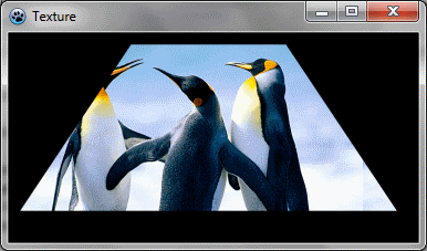 | |
| 36 | 33 | ||
| 37 | 34 | Wie Sie sehen ist das Bild nicht verformt. | |
| 38 | 35 | ||
| 39 | 36 | ### Affine Transformation | |
| 40 | 37 | ||
| 41 | 38 | Wir können aber auch eine affine Transformation anwenden, wie folgt: | |
| 42 | 39 | ||
| 43 | 40 | ``` pascal | |
| 44 | 41 | uses BGRABitmap, BGRABitmapTypes, BGRATransform; | |
| 45 | 42 | ||
| 46 | 43 | procedure TForm1.PaintImage; | |
| 47 | 44 | var image: TBGRABitmap; | |
| 48 | 45 | tex: TBGRABitmap; | |
| 49 | 46 | affine: TBGRAAffineBitmapTransform; | |
| 50 | 47 | ||
| 51 | 48 | begin | |
| 52 | 49 | //schwarzer Hintergrund | |
| 53 | 50 | image := TBGRABitmap.Create(ClientWidth,ClientHeight, BGRABlack ); | |
| 54 | 51 | ||
| 55 | 52 | tex:= TBGRABitmap.Create('image.png'); //lade eine Bitmap | |
| 56 | 53 | ||
| 57 | 54 | //create a rotation of 45° | |
| 58 | 55 | affine := TBGRAAffineBitmapTransform.Create(tex,True); | |
| 59 | 56 | affine.RotateDeg(45); | |
| 60 | 57 | ||
| 61 | 58 | //nimm diese Transformation als Parameter anstelle von 'tex' | |
| 62 | 59 | image.FillPolyAntialias( [PointF(110,10), PointF(250,10), PointF(350,160), PointF(10,160)], affine); | |
| 63 | 60 | ||
| 64 | 61 | affine.Free; | |
| 65 | 62 | tex.Free; | |
| 66 | 63 | ||
| 67 | 64 | image.Draw(Canvas,0,0,True); //auf dem Bildschirm zeichnen | |
| 68 | 65 | image.free; | |
| 69 | 66 | end; | |
| 70 | 67 | ``` | |
| 71 | 68 | ||
| 72 | 69 | ### Starten Sie das Programm | |
| 73 | 70 | ||
| 74 | 71 | Sie erhalten ein gedrehtes Bild in dem Polygon: | |
| 75 | 72 | ||
| 76 | - | ||
| 77 | - | ||
| 78 | - | ||
| 79 | - | ||
| 73 | + | 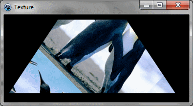 | |
| 80 | 74 | ||
| 81 | 75 | ### Texturen-Mapping | |
| 82 | 76 | ||
| 83 | 77 | Wenn die Textur an der Polygonlinie ausgerichtet sein soll, dann setzen wir ein Textur-Mapping ein. | |
| 84 | 78 | ||
| 85 | 79 | #### Lineares Mapping | |
| 86 | 80 | ||
| 87 | 81 | Lineares Mapping streckt das Bild linear bis zu den Rändern. Dazu schreiben wir: | |
| 88 | 82 | ||
| 89 | 83 | ``` pascal | |
| 90 | 84 | procedure TForm1.PaintImage; | |
| 91 | 85 | var image: TBGRABitmap; | |
| 92 | 86 | tex: TBGRABitmap; | |
| 93 | 87 | begin | |
| 94 | 88 | image := TBGRABitmap.Create(ClientWidth,ClientHeight, BGRABlack ); | |
| 95 | 89 | ||
| 96 | 90 | tex:= TBGRABitmap.Create('image.png'); | |
| 97 | 91 | image.FillPolyLinearMapping( [PointF(110,10), PointF(250,10), PointF(350,160), PointF(10,160)], tex, | |
| 98 | 92 | [PointF(0,0), PointF(tex.width-1,0), PointF(tex.Width-1,tex.Height-1), PointF(0,tex.Height-1)], true); | |
| 99 | 93 | tex.Free; | |
| 100 | 94 | ||
| 101 | 95 | image.Draw(Canvas,0,0,True); | |
| 102 | 96 | image.free; | |
| 103 | 97 | end; | |
| 104 | 98 | ``` | |
| 105 | 99 | ||
| 106 | 100 | Für das Mapping benutzen wir die Prozedur 'FillPolyLinearMapping'. Einige Parameter sind neu. Die Texturkoordinaten legen für jeden Punkt des Polygons die Lage in der Textur fest. Die letzte Option 'Interpolation' liefert uns die beste Qualität. | |
| 107 | 101 | ||
| 108 | 102 | ### Starten Sie das Programm | |
| 109 | 103 | ||
| 110 | 104 | Jetzt ist die Textur verformt, passend zur Form des Polygons. | |
| 111 | 105 | ||
| 112 | - | ||
| 113 | - | ||
| 114 | - | ||
| 115 | - | ||
| 106 | + | 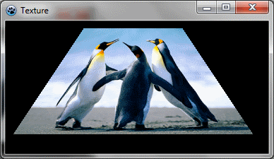 | |
| 116 | 107 | ||
| 117 | 108 | #### Perspektives Mapping | |
| 118 | 109 | ||
| 119 | 110 | Das perspektive Mapping erlaubt es, die Tiefe eines jeden Punktes zu ändern. | |
| 120 | 111 | ||
| 121 | 112 | ``` pascal | |
| 122 | 113 | procedure TForm1.PaintImage; | |
| 123 | 114 | var image: TBGRABitmap; | |
| 124 | 115 | tex: TBGRABitmap; | |
| 125 | 116 | begin | |
| 126 | 117 | image := TBGRABitmap.Create(ClientWidth,ClientHeight, BGRABlack ); | |
| 127 | 118 | ||
| 128 | 119 | tex:= TBGRABitmap.Create('image.png'); | |
| 129 | 120 | image.FillPolyPerspectiveMapping( [PointF(110,10), PointF(250,10), PointF(350,160), PointF(10,160)], | |
| 130 | 121 | [75, 75, 50, 50], | |
| 131 | 122 | tex, [PointF(0,0), PointF(tex.width-1,0), PointF(tex.Width-1,tex.Height-1), PointF(0,tex.Height-1)], true); | |
| 132 | 123 | tex.Free; | |
| 133 | 124 | ||
| 134 | 125 | image.Draw(Canvas,0,0,True); | |
| 135 | 126 | image.free; | |
| 136 | 127 | end; | |
| 137 | 128 | ``` | |
| 138 | 129 | ||
| 139 | 130 | Hier ist die Tiefe an der Polygonoberseite 75, am unteren Rand des Polygons bei 50. Dies bedeutet, dass die Unterseite näher beim Betrachter liegt, so als ob die Fläche horizontal wäre (wie ein Fussboden). | |
| 140 | 131 | ||
| 141 | 132 | ### Starten Sie das Programm | |
| 142 | 133 | ||
| 143 | 134 | Jetzt scheint es sich um ein 3D-Polygon zu handeln: | |
| 144 | 135 | ||
| 145 | - | ||
| 146 | - | ||
| 147 | - | ||
| 148 | - | ||
| 136 | + | 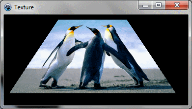 | |
| 149 | 137 | ||
| 150 | 138 | ### Schlussfolgerungen | |
| 151 | 139 | ||
| 152 | 140 | Mittels dieser Techniken ist es möglich, ein Bild zu verformen - wie in LazPaints Werkzeug "Gitterverformung" ("grid deformation") - oder 3D-Objekte mit Texturen darzustellen, wie in den Tests 19-21 der Funktion 'testbgrafunc' (ebenfalls im LazPaint-Archiv enthalten). | |
| 153 | 141 | ||
| 154 | 142 | [[BGRABitmap tutorial 9/de|Voriges Tutorial (Phong-Schattierung)]] \| [[BGRABitmap tutorial 11/de|Nächstes Tutorial (Kombinieren von Transformationen)]] | |
| 155 | 143 | ||
| 156 | 144 | --- | |
| 157 | 145 | *From the Free Pascal wiki, page "BGRABitmap tutorial 10/de", as it stood on 2020-02-09 after a change by Trev, out of the wiki's dump of 2024-05-26. Copyright stays with the author who wrote it, according to the old wiki's [[Licensing]] page. If you have concerns about this material, [message the admin](/wiki-contact).* |